Choosing the right Ev Charger Tester in 2026 is about more than checking whether a charging station powers on. A dependable tester can help technicians assess charging behavior, communication signals, and selected electrical readings before a unit is returned to service. Capabilities vary widely. Some models support particular connector types or charging modes, while others provide broader diagnostic functions. Check the specifications carefully.
A useful evaluation starts with the work at hand. Does the tester simulate a vehicle connection? Can it display control-pilot behavior or help verify protective functions? Are its connectors compatible with the stations you maintain? These details matter when a charger shows an error, a session stops unexpectedly, or a commissioning check needs a clear record. Small display labels and cable limits count, too. They can slow a job down.
Safety and documentation deserve equal attention. Follow the tester and charger manufacturers’ instructions, and use appropriately qualified personnel for electrical testing. A tester is a diagnostic aid, not proof that every installation condition is correct. No single device reveals every fault. That part is easy to forget. This guide compares practical features, usability, compatibility, and value to help identify an EV charger tester suited to real service needs. Some trade-offs are not obvious from a product page, so verify supported functions before buying.
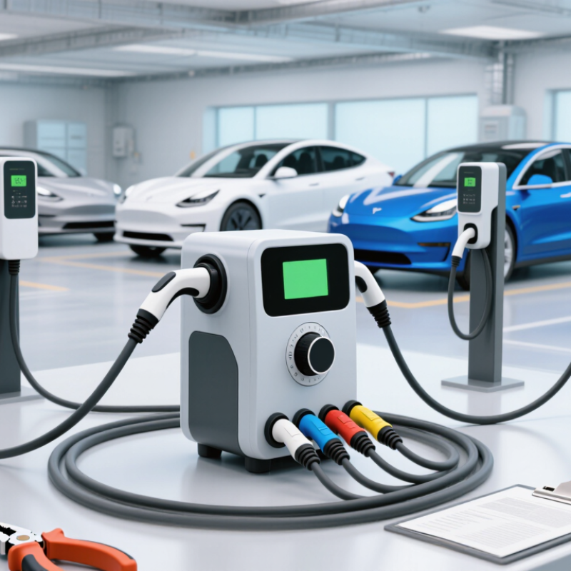
At an EV charging station, a tester checks whether the charger responds correctly when a vehicle is connected. It can simulate plug-in and charging states through the control pilot signal. The display may show the detected state, signal duty cycle, or available current. These readings help technicians spot a charger that never enables charging or advertises an unexpected limit.
A tester can also check connector wiring, protective-earth continuity, and supply voltage, depending on its design. Some units indicate whether the charger’s contactor has switched power to the outlet. A technician might compare that reading with a separate meter and inspect the connector for heat damage or loose pins. Small details matter. A slightly bent pin can interrupt a session even when the screen looks normal.
Not every tester measures insulation resistance or leakage current, so its scope should be checked before relying on it. Those checks may require separate, suitable instruments and trained handling. Readings should be compared with the station’s specifications, not treated as a universal pass mark. A tester is not magic. I have seen diagnostics feel reassuring, then miss a worn latch or intermittent cable fault. Visual inspection and repeat testing after a repair still matter.
An EV charger tester checks whether a charging station responds safely before a vehicle relies on it. It can simulate a vehicle connection through control-pilot and proximity signals. The tester then checks whether charging starts, pauses, and stops as expected. Small details matter. A loose connector or unexpected status change can reveal a problem.
For safety checks, technicians may use the tester to examine protective earth continuity and verify residual-current protection trips under specified test conditions. Some testers also measure voltage, current, and phase behavior while a controlled load is applied. These readings help identify faults such as unstable output or a charger that fails to deliver its configured current. Testing should follow the equipment instructions and be performed by qualified personnel; incorrect connections can create hazards.
Performance readings are useful, but they are only a snapshot. Results can vary with the supply, cable condition, temperature, and test setup. A passed test does not prove that every vehicle will charge perfectly. That limitation is easy to overlook. Record the test conditions alongside the readings, and investigate odd results rather than repeating tests until one looks reassuring.
2026 Best EV Charger Tester for EV Charging Stations?
Key Features to Compare in 2026 EV Charger Testers
Choosing a tester starts with the charging equipment it must verify. Check support for AC and DC chargers, connector types, and control-pilot and proximity-pilot signals. A useful unit should measure voltage and current, simulate a connected vehicle, and help assess protective functions. For field work, clear status indicators and readable results matter in bright daylight, noisy service bays, and cramped cabinets.
Safety and traceability deserve equal attention. Compare measurement ranges, electrical safety ratings, calibration documentation, and data logging. The International Energy Agency’s Global EV Outlook 2025 reports that public charging points grew by more than 1.3 million in 2024, reaching over five million worldwide. More sites mean more varied equipment to inspect. Still, a feature list alone cannot prove a tester suits a particular workflow.
Look for sturdy leads, replaceable accessories, and records that can be exported for maintenance reports. The IEA’s Global EV Outlook 2024 found public charging points rose about 40% in 2023, while fast chargers grew about 55%. That growth makes fast-charger compatibility especially relevant. A screen can look reassuring. It cannot replace careful setup, sound training, or periodic calibration; even experienced technicians can miss a loose connection when rushed.
EV Charger Tester Feature: Control Pilot (CP) State Verification
IEC 61851-1 defines nominal positive CP voltage levels of approximately +12 V, +9 V, +6 V, and +3 V for states A, B, C, and D. A tester can use these levels to verify connection and charging-state signaling. State D indicates that ventilation is required.
Choosing a tester starts with the station’s output, connector, and commissioning needs. AC stations usually need a tester that simulates a vehicle and checks control-pilot and proximity signals. It should also help verify protective-earth continuity and supported residual-current protection functions. Check that its voltage and current ratings match the equipment being tested. A clear fault indication matters when readings are taken in a noisy service area.
DC testing needs different capabilities. Confirm support for the station’s connector and communication protocol, along with suitable high-voltage ratings. Depending on the test plan, useful functions may include checking insulation-monitoring behavior, communication handshakes, and output measurements. Do not assume one device covers every DC configuration. Review the tester’s manual and the station’s specifications before connecting anything. Safety ratings are not optional.
Look at usability, too. A readable screen, secure leads, and saved test records can reduce mistakes during repeat checks. Calibration information and traceable results make reports more dependable. A low price can be tempting. But a tester that cannot reproduce the needed fault conditions may leave important gaps. Real installations vary, and no single checklist fits every site; that deserves a second look.
| Selection Dimension | AC Charging Station Tester | DC Charging Station Tester | What to Check Before Buying |
|---|---|---|---|
| Primary test purpose | Checks charging-station control signals, selected electrical functions, and operation with a simulated vehicle connection. | Checks DC charging control and communication; power-transfer testing may require a vehicle simulator, load equipment, or other dedicated test system. | Match the tester to commissioning, troubleshooting, periodic inspection, or laboratory testing. A basic adapter is not necessarily a complete diagnostic system. |
| Charging modes and connectors | Common coverage includes IEC 61851 AC charging and Type 1 or Type 2 interfaces, depending on the tester and region. | Coverage may include CCS interfaces; confirm the exact connector version and communication functions supported by the equipment. | Check the station’s connector type, region, cable arrangement, and whether adapters are included and rated for the intended use. |
| Voltage and frequency range | Many installations use 230 V single-phase or 400 V three-phase AC at 50 or 60 Hz. Actual values depend on the local supply. | DC station output ranges vary by equipment. Some systems are designed for outputs up to 1,000 V DC; not every station or tester supports that range. | Verify the tester’s stated operating and measurement limits against the station’s maximum output. Never assume an adapter’s rating covers the station. |
| Control and communication checks | Look for control-pilot (CP) state simulation and, where relevant, proximity-pilot (PP) checks. Available functions vary by tester. | Look for the required vehicle-to-charger communication simulation and protocol support for the station under test. | Confirm which signals, states, and protocol stages are actually tested, rather than relying on a general “compatibility” claim. |
| Electrical measurements | Useful functions can include supply voltage, phase sequence, protective-earth checks, and measurement support through compatible instruments. | Check whether the system measures DC output or only verifies communication and control. High-voltage output testing requires equipment specifically rated for it. | Review measurement ranges, accuracy, test method, and whether separate meters, probes, or current clamps are required. |
| Protective-device testing | Some test setups support RCD testing or connection to an external RCD tester. EV installation protection can involve AC and residual DC considerations. | Protection checks depend on the station design and applicable installation rules; a charging simulator alone may not verify all protective functions. | Check the relevant local code and the tester’s supported RCD tests. Requirements differ by jurisdiction and installation type. |
| Safety rating and isolation | Choose equipment with clearly stated electrical ratings, appropriate measurement category where applicable, and suitable leads and connectors. | Confirm DC voltage, transient, connector, and isolation ratings for every part of the test setup. | Read the instrument’s safety markings and manual. Do not connect equipment beyond its marked limits or use a tester as a substitute for safe isolation procedures. |
| Standards and documentation | IEC 61851-1 covers general requirements for conductive charging systems; IEC 62196 covers plugs, socket-outlets, vehicle connectors, and inlets. | IEC 61851-23 addresses DC EV supply equipment, while IEC 61851-24 addresses digital communication between DC EV supply equipment and vehicles. | Standards editions and national adoptions can differ. Check the tester documentation and the standards applicable to the project. |
| Results and reporting | Basic units may show pass/fail or measured values; advanced setups may store readings and create reports. | For protocol or power testing, look for traceable logs, fault information, and exportable test results where required. | Choose the reporting detail needed for service records, commissioning records, or compliance documentation. |
| Best fit | Routine checks and troubleshooting of AC stations when the required connector, pilot, and electrical tests are supported. | Specialist commissioning or diagnosis where DC communication and, if needed, high-voltage power-transfer testing are covered by the complete setup. | For mixed AC/DC sites, compare the cost and capability of one integrated system with separate purpose-built test equipment. |
Selection note: “Best” depends on the station type, local requirements, test scope, and safety ratings. Confirm capabilities and limits in the tester’s technical documentation before use.
A reliable test begins with the right setup. Match the tester to the charger’s connector and charging mode, then inspect its leads, casing, and display for damage. Keep the work area dry and follow the tester’s instructions. Small checks matter.
For a station check, use the tester to confirm functions such as control-pilot response, protective-earth continuity, and fault indication, where supported. Compare readings with the charger’s specifications and applicable IEC 61851 requirements. Testing is not a substitute for qualified electrical work or a full station inspection.
Routine care keeps results useful. Clean contacts with a dry, lint-free cloth; never force a connector or open the tester casing. Store it away from moisture, dust, and vehicle traffic. Record the date, charger ID, readings, and any unusual behavior. Arrange calibration at the interval specified by the manufacturer, and remove a damaged or overdue unit from service.
The IEA’s Global EV Outlook 2024 reported that public charging points grew by about 40% in 2023, surpassing four million worldwide. With networks expanding, consistent checks help technicians spot faults early. Still, a passing tester result does not prove every charging session will be trouble-free.
„Thanks to the LUVIR technology, the solder resist process could be switched directly from the previously used mask exposure to direct exposure. As an outstanding digital solution on the market, this technology has been able to demonstrate fast process times and superior quality on our certified conventional ink in production. This allowed us to fully digitize the solder mask process at low cost – without process or ink adjustments. An excellent benefit to our production in Rot am See.“
Ralf Göhringer (Head of Production WE Rot am See)
I would definitely recommend the Limata machine and team for a future company purchase
Michael Greenaway
Compunetics Inc.
“The Limata ldi has been amazing!! Best thing we did was buy this machine”
Richard Brady
GM
Circuitlabs
“Since 2019, we have been running the Limata X1000 LDI system (including LUVIR for solder mask imaging) in daily production as an addition to our current process with film. The machine was capable of properly exposing Taiyo PSR-4000 BN (DI) solder mask types on normal to high-copper boards using a new and unique direct imaging process. The machine operating interface is very user friendly which allowed for a quick technical training curve. The pre-registration processing reduced several seconds of production time at every print. Limata support and service staff is incomparable. They supported our team every step of the way at basically any time of the day or night, with literally, an immediate response time, customizing the software interface to best fit our Operations and needs.
We have exposed more than 8,000 prints since end of October, on various solder mask colors and some resist film panels. Limata, has proven to be very capable and innovative. They are a strong contender in the industry.
We have very much enjoyed this project, and working with the team!
Thank you Limata for the continued support and being a part of our growth.”
Bill Sezate
Vice President, GM
Summit Interconnect
As a replacement to our current contact exposure process with film, the LIMATA X2000 system including LUVIR-Technology was capable of properly exposing non-LDI solder mask types using a direct imaging process. The machine offers cutting edge software with a very intuitive operating interface which allowed for quick technician training curve. The dual drawer system combined with pre-registration processing reduced several seconds of production time at every machine cycle. Limata support and service staff is world class. They added software patches to keep production running at shortest possible response times, customized the software interface to best fit our in-house Operations system, and even wrote a step-by-step machine processing manual. As a result of the project, we have exposed more than 16,000 times on various product types and solder mask brands/colors. Limata, in a very short timeframe as a company, has definitely shown they are truly innovative and will be challenging the industry of direct imaging for the top spot.
Kevin Beattie
Process Engineer
TTM Technologies
Forest Grove Division
