Choosing the best Remote Io Module for industrial automation in 2026 starts with the machine, not a product ranking. A packaging line with sensors across several stations has different needs from a pump skid in a damp utility room. The right module should match the controller’s communication protocol, required channel count, signal types, and available power. Check these details against current manufacturer documentation.
Look beyond the headline specifications. Review isolation, operating temperature, ingress protection, diagnostics, configuration tools, and support for replacement modules. Clear channel status indicators can help a technician trace a disconnected sensor at a cabinet without guessing. That matters. Compatibility deserves equal attention: a module may support a familiar network yet still require specific firmware, software, or couplers. Verify this before ordering.
This guide compares practical selection criteria and explains where common module types fit. It also considers installation effort, expansion capacity, and lifecycle support, since a low purchase price may not mean lower total cost. For a fair comparison, use the same application requirements for every candidate and confirm claims in datasheets or technical manuals. There is no universal winner. Even a well-matched module can disappoint when grounding, wiring, or network settings are overlooked. That part is easy to underestimate. The aim is not to name a perfect device, but to help readers make a defensible choice for their actual control system.
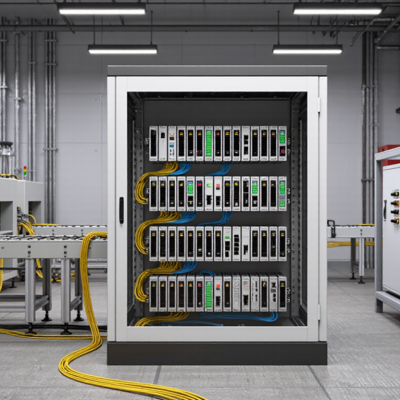
Remote I/O moves input and output connections closer to sensors, motors, valves, and other field devices. A local module collects signals, then communicates them to a controller over an industrial network. The controller can read a temperature probe and command a nearby valve without routing every wire back to one central cabinet. That means less long-distance cabling and clearer machine layouts. It also means network quality matters.
Inputs report conditions, such as a photoelectric sensor detecting a box on a conveyor. Outputs trigger actions, such as opening a pneumatic valve. Some modules also support local processing or diagnostics, but their exact capabilities vary. Check signal types, channel count, response time, isolation, and operating temperature against the machine’s real needs.
A specification sheet cannot reveal every installation challenge. Cable routing and electrical noise still deserve attention.
Tips: Label channels at both ends. Test signal behavior before startup. Leave spare capacity, but avoid paying for unused features. A tidy layout helps, though it does not guarantee easy troubleshooting.
Distributed control can reduce wiring complexity, yet it adds network devices that technicians must understand. During commissioning, verify each field signal at the module and at the controller. If a sensor reading is delayed or unstable, inspect the connection, configuration, and surrounding electrical environment. The “best” remote I/O choice is the one that fits the process and remains practical to maintain.
A remote I/O module can carry a 24 V DC label and still be a poor fit for a control panel. Check the input thresholds, permitted voltage range, and channel configuration against the sensors actually installed. A three-wire proximity sensor, for example, may need a sourcing input and a shared reference. Small wiring differences matter.
IEC 61131-2:2017 sets equipment requirements and test methods for programmable controllers and associated peripherals. Treat a compliance statement as a starting point, not a substitute for checking the evidence. Confirm which requirements apply to the module and whether documentation covers the relevant model and configuration. The standard does not tell you whether a specific channel can handle your field load. That matters.
For outputs, compare rated current with the real load, including startup current and switching frequency. Check leakage current, isolation, and any temperature derating; a crowded cabinet can run warmer than expected. Review common-terminal limits too. A datasheet may list a generous per-channel rating while imposing a lower group limit. I would not choose on headline numbers alone. Even a tidy specification can leave wiring questions unanswered, so verify terminal diagrams before installation.
| Selection Dimension | Recommended Evaluation Criteria | What to Verify in the Datasheet or Test Report | Why It Matters |
|---|---|---|---|
| IEC 61131-2:2017 conformity | Require an explicit conformity statement for the applicable module and I/O types. | Check the stated edition, applicable input/output types, test scope, and supporting declaration or report. Do not infer conformity from a general “IEC 61131” reference. | The standard specifies functional and EMC requirements and associated tests for programmable controllers and peripherals; the precise claim and scope should be documented. |
| Digital input voltage | For a 24 V DC system, select inputs specified for the intended 24 V DC signal and compatible with the field-device output. | Verify the rated voltage, permitted operating range, input thresholds, input current, and supported IEC input type. Compare these values with the sensor’s ON/OFF output levels. | “24 V DC” is a nominal system value, not a complete description of the input’s acceptable voltage or switching behavior. |
| Digital output type and load | Match the output technology and wiring arrangement to the load—for example, sourcing or sinking DC outputs where applicable. | Check rated load voltage, maximum current per channel and per module, short-circuit or overload protection, leakage current, and switching limits. | These ratings determine whether the module can switch the intended actuators and whether external protection or interposing devices are needed. |
| Channel count and isolation | Choose the channel density and isolation arrangement to suit the panel layout, signal grouping, and fault-containment needs. | Confirm channel count, isolation between channels or groups, common-terminal arrangement, and any derating rules for simultaneous operation. | Higher density can reduce cabinet space, while grouping and isolation affect wiring, troubleshooting, and the impact of a channel fault. |
| Analog I/O capability | Specify only the signal types and resolution required by the application. | For each channel, verify supported ranges (such as current or voltage ranges), resolution, accuracy, update time, input impedance or output load limits, and isolation. | Analog signal ranges and performance vary by module; they should be matched to the instrument and required measurement or control accuracy. |
| Remote I/O network | Confirm compatibility with the controller’s fieldbus or industrial Ethernet system. | Check supported protocol and revision, network topology, device-description files, update-time options, addressing, and controller interoperability evidence. | A module’s I/O ratings do not guarantee that it can communicate with a particular controller or meet the application’s network timing needs. |
| Diagnostics and fault response | Prefer channel-level status and clear behavior during communication or power faults. | Review diagnostic coverage, LED indicators, reported fault codes, substitute-value behavior, watchdog response, and recovery behavior after reconnection. | Useful diagnostics can reduce commissioning time and help operators identify wiring, load, or network problems. |
| Power and environmental limits | Check that the module’s supply, installation, and environmental ratings match the cabinet and site conditions. | Verify supply-voltage limits, power consumption, operating temperature, humidity limits, mounting requirements, and any enclosure or contamination restrictions. | Environmental and power limits affect reliability and may require cabinet cooling, protective enclosures, or additional power supplies. |
| Safety and application suitability | Do not treat standard remote I/O as safety-rated unless the specific hardware and system are certified for the required safety function. | For safety-related applications, confirm the applicable safety certification, permitted architecture, configuration requirements, and limits in the safety manual. | IEC 61131-2 conformity alone does not establish suitability for a safety function. |
Selection note: There is no universally “best” remote I/O module. Confirm every electrical rating, standards claim, and compatibility requirement against the exact module datasheet and applicable test documentation before selection.
2026 Best Remote IO Module for Industrial Automation?
Choosing a remote I/O module starts with the network already used on the plant floor. Modbus TCP communicates over Ethernet and commonly uses TCP port 502. It suits straightforward register-based data exchange, such as reading a tank-level value or switching a valve output. Check device limits, register mapping, and network access controls; an open port alone does not guarantee reliable communication. Port discipline matters.
The 2024 Industrial Network Market Shares report estimated PROFINET at 23%, EtherCAT at 16%, and Modbus TCP at 6% of newly installed industrial Ethernet nodes. These are market estimates, not a measure of technical superiority. PROFINET is a practical fit for distributed automation with cyclic data and detailed diagnostics. EtherCAT supports tightly synchronized, fast control loops, but its topology and configuration need careful planning. A gateway can connect unlike networks, yet may add delay and complicate troubleshooting. A missed detail.
Compare update time, redundancy needs, diagnostic visibility, and controller support before choosing. Then test the actual I/O load: watch for dropped updates while a drive starts and several sensor values change together. A clean bench test can still miss cabinet noise or switch congestion. Keep those limits in view.
A remote I/O module’s update time should be judged under load, not from a best-case datasheet figure. For a fast-moving conveyor, a 2 ms input-to-network cycle may matter; for a slow tank-level signal, 20 ms may be adequate. These are design targets, not universal limits. Measure the complete path, including sensor filtering, module scanning, switch delays, and controller processing. Small delays add up.
A 100 Mbps Ethernet port describes link speed, not usable process-data throughput. Packet overhead and network traffic reduce the capacity available to I/O. HMS Networks’ 2024 Industrial Network Market Shares report estimated industrial Ethernet at 71% of newly installed nodes, showing why Ethernet performance is increasingly relevant. Node capacity still varies by protocol, packet size, update rate, and controller limits; there is no meaningful universal maximum. Test the expected node count with realistic traffic and watch for missed updates. A tidy specification can mislead. I have seen designs overlook diagnostic traffic, then wonder why timing drifts. Check performance at the busiest point, not just on an empty bench.
Representative engineering ranges for 100 Mbps Ethernet remote I/O systems. Actual update time and node limits depend on the protocol, network load, configuration, and device specifications; these values are illustrative, not a vendor benchmark.
For selection, compare update time at the required I/O payload and network load, then verify the supported node count and 100 Mbps Ethernet compatibility in the device documentation.
For remote I/O in 2026, “best” depends on how well a module fits the hazards and maintenance routines at a specific site. Check isolation, channel-level fault behavior, and whether safety-rated signals require separate hardware. A clear wiring diagram matters. During a cabinet inspection, technicians should be able to trace a sensor lead without guessing which channel has failed.
Diagnostics can shorten downtime when they show more than a generic fault. Look for per-channel status, useful event records, and clear indicators for communication loss or an open circuit. Can staff identify a failed input from the controller display, or must they open the panel with a meter? That difference matters at 2 a.m. Still, more diagnostic data is not automatically better; alarms need sensible filtering.
Lifecycle support deserves equal weight. Confirm the module’s documented service life, firmware policy, spare availability, and migration options before a line depends on it. A low purchase price can become expensive when replacement requires rewiring dozens of terminals. Ask how configuration files are backed up and restored, then test the process. It may expose an awkward gap. I may be overvaluing replaceability, but a stocked spare and readable records can matter more than one extra feature.
„Thanks to the LUVIR technology, the solder resist process could be switched directly from the previously used mask exposure to direct exposure. As an outstanding digital solution on the market, this technology has been able to demonstrate fast process times and superior quality on our certified conventional ink in production. This allowed us to fully digitize the solder mask process at low cost – without process or ink adjustments. An excellent benefit to our production in Rot am See.“
Ralf Göhringer (Head of Production WE Rot am See)
I would definitely recommend the Limata machine and team for a future company purchase
Michael Greenaway
Compunetics Inc.
“The Limata ldi has been amazing!! Best thing we did was buy this machine”
Richard Brady
GM
Circuitlabs
“Since 2019, we have been running the Limata X1000 LDI system (including LUVIR for solder mask imaging) in daily production as an addition to our current process with film. The machine was capable of properly exposing Taiyo PSR-4000 BN (DI) solder mask types on normal to high-copper boards using a new and unique direct imaging process. The machine operating interface is very user friendly which allowed for a quick technical training curve. The pre-registration processing reduced several seconds of production time at every print. Limata support and service staff is incomparable. They supported our team every step of the way at basically any time of the day or night, with literally, an immediate response time, customizing the software interface to best fit our Operations and needs.
We have exposed more than 8,000 prints since end of October, on various solder mask colors and some resist film panels. Limata, has proven to be very capable and innovative. They are a strong contender in the industry.
We have very much enjoyed this project, and working with the team!
Thank you Limata for the continued support and being a part of our growth.”
Bill Sezate
Vice President, GM
Summit Interconnect
As a replacement to our current contact exposure process with film, the LIMATA X2000 system including LUVIR-Technology was capable of properly exposing non-LDI solder mask types using a direct imaging process. The machine offers cutting edge software with a very intuitive operating interface which allowed for quick technician training curve. The dual drawer system combined with pre-registration processing reduced several seconds of production time at every machine cycle. Limata support and service staff is world class. They added software patches to keep production running at shortest possible response times, customized the software interface to best fit our in-house Operations system, and even wrote a step-by-step machine processing manual. As a result of the project, we have exposed more than 16,000 times on various product types and solder mask brands/colors. Limata, in a very short timeframe as a company, has definitely shown they are truly innovative and will be challenging the industry of direct imaging for the top spot.
Kevin Beattie
Process Engineer
TTM Technologies
Forest Grove Division
