Choosing an Inspection Machine For Printing is rarely a simple equipment purchase. It affects waste, customer trust, production speed, and daily operator decisions. A glossy brochure may promise perfect detection, but real pressrooms are less forgiving. Dust appears. Ink density shifts. Reflective film confuses cameras.
A reliable choice begins with the actual production environment. Consider web width, line speed, substrate texture, print contrast, and the smallest defect that matters commercially. A machine designed for paper labels may struggle with transparent films or metallic packaging. Check camera resolution, lighting control, software stability, and compatibility with existing presses. Ask for a live demonstration using your own difficult materials. Sample rolls reveal more than polished presentations.
Quality expert Joseph M. Juran said, “Quality does not happen by accident.” His observation remains practical for modern print inspection. A strong Inspection Machine For Printing should detect missing text, color variation, spots, streaks, and registration errors without overwhelming operators with false alarms. It should also record images and defect data clearly. That evidence supports root-cause analysis, not just rejection.
Do not ignore maintenance. A dirty lens can create expensive confusion. Training matters too. Even advanced systems fail when settings are poorly understood. The cheapest machine may become the costliest after repeated downtime, rejected rolls, and frustrated staff. Still, no system is perfect. Detection thresholds require testing, adjustment, and honest review. These seven tips offer a grounded way to compare performance, usability, integration, support, and long-term value before signing a purchase order.
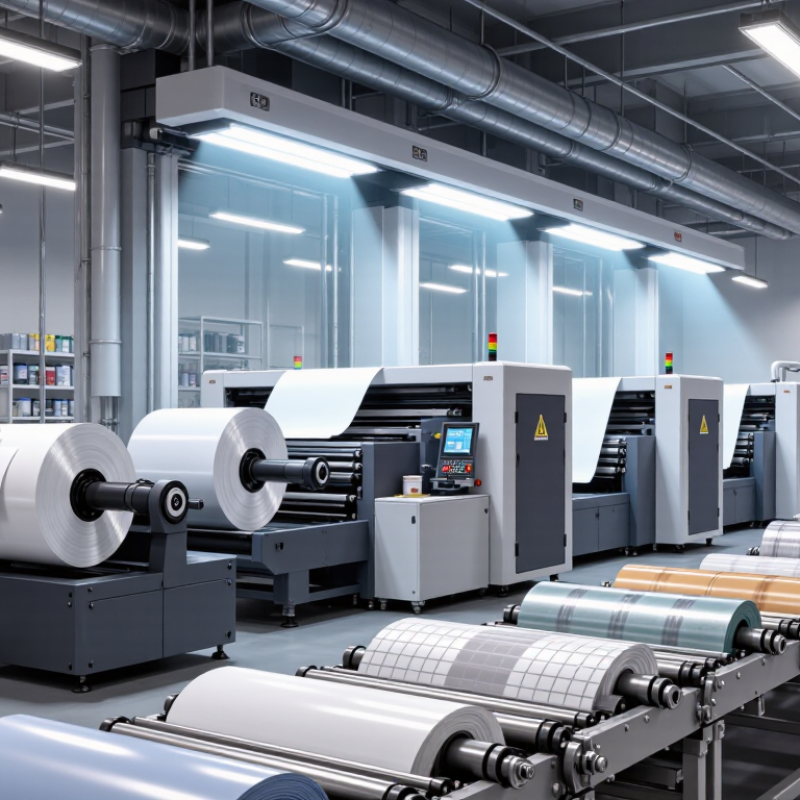
Define the inspection scope before comparing machines. A 100% web inspection system checks every printed meter while the press runs. It can detect missing text, color streaks, pinholes, and registration shifts. This approach suits labels, films, and safety-critical packaging. One missed defect can travel through an entire roll.
Tip 1: Match the camera width to the real web width. Confirm resolution, lighting stability, and inspection speed under production conditions.
Tip 2: Test difficult samples, including metallic areas, dark backgrounds, fine text, and spliced rolls. A clean sample proves very little. Ask how the system handles false alarms and unclear images.
ISO 2859-1 sampling serves a different purpose. It evaluates selected units from a defined lot using acceptance criteria. It does not inspect every printed section. AQL is not a guaranteed quality level, and sampling may overlook short defects between samples. Set the lot size, inspection level, and acceptance number with qualified quality staff.
Tip 3: Choose a machine that records sample results, defect images, operator actions, and calibration checks. Keep lighting and camera settings controlled.
In practice, teams sometimes choose sampling because it costs less, then discover that defect location data is missing. That decision deserves a second look.
A reliable inspection machine starts with measurable print targets. ISO 12647-2 provides reference conditions for offset printing, including substrate, tone value, and process colors. Do not treat it as a generic “good print” label. Paper whiteness and surface finish can shift readings. Record the approved stock, ink sequence, and measurement geometry before setting machine limits.
Use ΔE00 to judge visible color differences more realistically than older ΔEab calculations. Fogra’s ProcessStandard Offset guidance supports instrument-based verification with control strips and standardized color data. Set separate limits for solids, tints, and critical brand colors. A practical starting point is ΔE00 ≤ 2.0 for key solids, but production capability should decide the final threshold. That number may be too strict on rough uncoated paper.
Registration needs physical limits, not visual guesses. Measure front-to-back, color-to-color, and image-to-die alignment across the sheet. Many quality teams begin near 0.10–0.15 mm for stable commercial offset work, then confirm capability through repeated samples. The 2023 State of the Industry reporting from PRINTING United Alliance highlights continuing pressure to reduce waste and rework, making early defect detection financially important. Still, a limit without sampling rules is incomplete. Define scan frequency, alarm delays, and operator response. Machines can measure perfectly and still miss the real problem.
Choosing an inspection machine for printing starts with three linked measurements: camera resolution, field of view, and line speed in m/min. A wider view usually reduces pixels per millimeter, while higher resolution may restrict coverage. Define the smallest defect that matters, such as a 0.3 mm missing dot, before selecting the sensor. Measure the actual web width, not only the nominal width. Measure it live.
For example, a 4,096-pixel line camera viewing a 1,600 mm web provides about 2.56 pixels per millimeter. At 120 m/min, the material travels two meters each second, so exposure time must be extremely short. Motion blur can hide fine streaks, even when resolution looks sufficient. Check lens distortion, lighting uniformity, encoder accuracy, and trigger timing together. A camera with impressive pixel numbers may still deliver weak images under uneven illumination.
Allow practical headroom. Running equipment continuously at its maximum rated speed leaves little margin for acceleration, splice detection, or vibration. Test samples at the fastest expected production speed, then inspect enlarged images for edge defects and registration shifts. I have seen specifications pass laboratory trials but struggle beside a warm, vibrating press. That experience is easy to overlook. Recheck the field of view after installation, because mounting height and web movement can change the usable inspection area. Reliable decisions come from measured pixels, stable illumination, and repeatable tests, not isolated catalog figures.
Choosing an inspection machine for printing starts with measurable defect performance, not a polished specification sheet. Minimum detectable size matters when a missing dot, pinhole, or fine streak can affect product quality. Ask whether the stated size applies to real production speed, not a quiet laboratory sample. A machine that detects 0.2 mm defects slowly may miss them at full web speed.
Contrast is equally important. A dark mark on a pale background is usually easier to detect than a faint shade shift. Test samples should include low-contrast defects, uneven ink coverage, glare, and textured materials. Use the same lighting, speed, and print density planned for production. Small details matter. Some tests look convincing but lack realistic variation.
False alarms can quietly damage productivity. If normal grain, dust, or registration movement triggers repeated stops, operators may begin ignoring alerts. Compare the false-alarm rate beside the true detection rate. Keep a defect log during a controlled trial, then review missed defects and unnecessary alarms separately. There is no perfect threshold. A highly sensitive setting may find more defects while creating too much noise. I would also question results based on only one roll or one defect type. More samples usually reveal weaknesses. Ask for repeatable evidence, clear test conditions, and an explanation of how the machine handles changing contrast during an actual print run.
Representative controlled-test values for printed materials. Lower values indicate better performance for all three metrics.
The comparison covers minimum detectable defect size, minimum visible contrast difference, and false-alarm rate. A suitable system should detect smaller defects, recognize lower-contrast variations, and minimize false alarms without reducing inspection coverage.
7 Tips to Choose an Inspection Machine for Printing
Evaluate integration before counting pixels. Tip 1: Check interfaces for your press, vision system, MES, and reject unit. The International Federation of Robotics reported 541,302 industrial robots were installed worldwide in 2023. Automation is expanding, but disconnected equipment still creates manual work. Tip 2: Confirm data ownership and export formats. Tip 3: Test whether every defect receives a timestamp, image, roll number, and operator record. Traceability should work during a real production dispute, not only during a demonstration.
Measure OEE impact at line speed. Tip 4: Define how inspection data will calculate availability, performance, and quality under ISO 22400 principles. A useful system identifies repeated stoppages, false rejects, and slow changeovers. The numbers must reach supervisors quickly. Tip 5: Run a controlled trial using normal dust, glare, splice marks, and variable substrates. Perfect samples are misleading. Tip 6: Estimate payback from verified losses, including waste, rework, complaints, and inspection labor. The World Economic Forum’s Future of Jobs Report 2023 found that 44% of workers’ skills may be disrupted within five years. Usability matters.
Tip 7: Ask for a conservative payback model. Use your last twelve months of data, not optimistic targets. Include training, integration, maintenance, calibration, and downtime. A practical test is simple: can one operator understand the alert in five seconds? If not, the machine may be technically advanced but operationally weak. Reflection is necessary. A fast camera cannot repair poor process control.
| Inspection Machine Profile | Typical Print Applications | Recommended Web Speed (m/min) | Inspection Resolution (mm/pixel) | Integration Readiness (1–5) | Traceability Capability (1–5) | Estimated OEE Improvement (percentage points) | Typical Payback (months) | Key Selection Consideration |
|---|---|---|---|---|---|---|---|---|
| Basic Offline Vision Inspection | Labels, flexible packaging samples, short runs | 0–60 | 0.10–0.20 | 2 | 2 | 1–2 | 18–30 | Suitable when inspection is needed away from the press and capital cost must remain low. |
| Inline Surface Inspection | Flexographic and gravure web printing | 100–250 | 0.15–0.30 | 4 | 3 | 2–4 | 12–24 | Prioritize stable triggering, low false-reject rates, and communication with the line PLC. |
| 100% Print-Quality Inspection System | Labels, cartons, flexible packaging, security print | 150–400 | 0.10–0.25 | 4 | 5 | 3–6 | 9–18 | Best for customers requiring defect maps, roll reports, job history, and audit-ready quality records. |
| Register and Color-Control Inspection | Multicolor packaging and high-quality commercial print | 150–350 | 0.10–0.20 | 4 | 4 | 3–5 | 10–20 | Evaluate color-reference management, register tolerance settings, and operator changeover time. |
| Variable-Data and Code Verification System | Track-and-trace labels, pharmaceutical and serialized packaging | 80–250 | 0.08–0.20 | 5 | 5 | 2–5 | 9–18 | Confirm database connectivity, code grading, duplicate detection, reject handling, and export formats. |
| AI-Assisted Defect Classification System | Complex packaging defects and variable cosmetic standards | 100–300 | 0.10–0.25 | 4 | 4 | 3–7 | 12–24 | Require representative training images, transparent confidence thresholds, and controls for model updates. |
| Closed-Loop Inspection and Process-Control System | High-volume packaging lines with automated correction | 200–500 | 0.08–0.20 | 5 | 5 | 5–10 | 12–30 | The strongest option for OEE improvement when inspection data can automatically adjust registration, ink, or process settings. |
„Thanks to the LUVIR technology, the solder resist process could be switched directly from the previously used mask exposure to direct exposure. As an outstanding digital solution on the market, this technology has been able to demonstrate fast process times and superior quality on our certified conventional ink in production. This allowed us to fully digitize the solder mask process at low cost – without process or ink adjustments. An excellent benefit to our production in Rot am See.“
Ralf Göhringer (Head of Production WE Rot am See)
I would definitely recommend the Limata machine and team for a future company purchase
Michael Greenaway
Compunetics Inc.
“The Limata ldi has been amazing!! Best thing we did was buy this machine”
Richard Brady
GM
Circuitlabs
“Since 2019, we have been running the Limata X1000 LDI system (including LUVIR for solder mask imaging) in daily production as an addition to our current process with film. The machine was capable of properly exposing Taiyo PSR-4000 BN (DI) solder mask types on normal to high-copper boards using a new and unique direct imaging process. The machine operating interface is very user friendly which allowed for a quick technical training curve. The pre-registration processing reduced several seconds of production time at every print. Limata support and service staff is incomparable. They supported our team every step of the way at basically any time of the day or night, with literally, an immediate response time, customizing the software interface to best fit our Operations and needs.
We have exposed more than 8,000 prints since end of October, on various solder mask colors and some resist film panels. Limata, has proven to be very capable and innovative. They are a strong contender in the industry.
We have very much enjoyed this project, and working with the team!
Thank you Limata for the continued support and being a part of our growth.”
Bill Sezate
Vice President, GM
Summit Interconnect
As a replacement to our current contact exposure process with film, the LIMATA X2000 system including LUVIR-Technology was capable of properly exposing non-LDI solder mask types using a direct imaging process. The machine offers cutting edge software with a very intuitive operating interface which allowed for quick technician training curve. The dual drawer system combined with pre-registration processing reduced several seconds of production time at every machine cycle. Limata support and service staff is world class. They added software patches to keep production running at shortest possible response times, customized the software interface to best fit our in-house Operations system, and even wrote a step-by-step machine processing manual. As a result of the project, we have exposed more than 16,000 times on various product types and solder mask brands/colors. Limata, in a very short timeframe as a company, has definitely shown they are truly innovative and will be challenging the industry of direct imaging for the top spot.
Kevin Beattie
Process Engineer
TTM Technologies
Forest Grove Division