Please provide the source article or the name and verified quotation of the industry expert you want included. No article was included here, and I can’t responsibly invent an expert attribution.
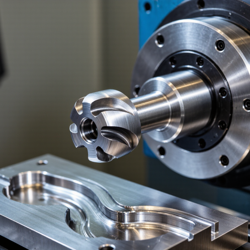
A ball end mill is a rotating cutting tool with a rounded, hemispherical tip. Its flutes run along the curved end and continue up the tool body, creating edges that can cut both the tip area and the sides. In profile, the end looks like half a sphere. A simple shape, but useful.
Unlike a flat end mill, the ball-shaped tip can follow curved surfaces and form smooth transitions. Machinists use it for three-dimensional contours, mold cavities, rounded grooves, and sculpted details. The ball radius determines how tightly the tool can reach into a curve. Smaller radii access finer features, though they may need more careful handling. Watch the toolpath. Near the very center of the tip, cutting speed is low, so the tool may rub instead of cutting cleanly. Stepover also matters: closer passes usually leave smaller ridges, but take longer. A ball end mill is not automatically the best choice for every surface; a flat cutter may work faster on broad, level areas. Tool reach, material, and machine rigidity can change the result, too.
A ball end mill has a rounded, hemispherical cutting tip that sweeps through material as the tool rotates. Its flutes carry chips away from the curved surface, leaving a smooth transition rather than a sharp corner. This shape is useful for machining curved molds, shallow channels, and three-dimensional contours. Small detail. The contact point moves across the tip as the tool follows the programmed path, so the cut changes with the tool’s angle and depth.
Near the center of the tip, cutting speed approaches zero. That can encourage rubbing instead of clean cutting, especially if the tool feeds too slowly or chips remain trapped. On a sloped surface, more of the ball’s side engages the workpiece, where cutting action is often stronger. A machinist may adjust tool orientation, feed rate, and stepover to balance finish quality with cutting time. Tighter stepovers usually leave smaller scallops, but they also add passes. Not always. A polished-looking surface can still show faint ridges under angled light, so inspection matters. The right settings depend on the material, tool size, machine rigidity, and actual setup; a toolpath that works well in one case may disappoint in another.
Ball end mills are used where a cutter must follow a curved surface rather than leave a flat floor. Their rounded tips suit 3D contouring, sculpted cavities, mold and die work, and finishing around fillets. On a steel mold insert, for example, a small ball nose can trace a shallow channel while preserving the rounded transition into the wall. It is also useful for finishing complex surfaces on aerospace and medical components, when the material and machining setup allow.
The tool’s shape has a trade-off. Cutting speed falls near the center of the tip, so a poor toolpath can rub instead of cut. Small stepovers improve the finish, but increase machining time. Not always. Grand View Research’s 2023 CNC Machine Market report estimated a global market value of $101.22 billion in 2022 and forecast 9.4% annual growth through 2030. That figure describes CNC equipment, not ball end mills specifically; it signals the expanding machining environment in which these tools are used. For a finish pass, check the surface under angled light and inspect the tool for wear. A smooth-looking path can still leave scallops. I would verify the result on a test piece before committing to a costly part.
Ball end mills are useful when a part has curved, sculpted, or intersecting surfaces. Their rounded tips can follow a mold cavity, machine a fillet, or blend a sloped wall into a floor. They are commonly used on aluminum, carbon and stainless steels, and titanium, with suitable tooling, speeds, and chip control. Plastics and graphite can also be machined, though heat, brittleness, or dust may call for different cutting conditions. The material alone does not determine the result; machine rigidity and toolpath matter too.
On 3D surfaces, the ball’s contact point shifts as the cutter moves. A small stepover can leave finer scallops, but it increases machining time. A larger stepover removes stock faster and may leave visible ridges that need finishing. Ball end mills suit detailed contours better than broad, flat areas, where a flat-bottom cutter may be more efficient. They are not always ideal. I would avoid assuming a smooth-looking toolpath guarantees a smooth part; runout, tool wear, and vibration can still mark the surface.
Tips: Match stepover to the finish you need, then inspect a test cut under angled light. Keep the tool engaged smoothly, and check for chip buildup in deep cavities. A little trial and error is normal.
A ball end mill selection depends on the surface, material, and machine setup—not just the cutter diameter. For curved mold cavities, its rounded tip can create smooth contours and reach into sculpted areas. The required finish matters too. A smaller stepover leaves finer surface marks, but increases machining time.
Match the tool diameter and corner radius to the smallest feature you need to cut. A smaller ball can reach tight curves, though it may deflect more under load. Long-reach tools access deep pockets but are less rigid. Short tools are steadier. Check flute count against the work material and chip space: aluminum often needs room for chip evacuation, while harder materials may benefit from a different cutting strategy. Tool material, coating, spindle speed, and feed rate also affect performance. A rigid holder and low runout help prevent uneven cutting. One easy detail to overlook is reach; a tool that barely clears a wall may chatter or leave a poor finish.
Tips: Choose the shortest tool that reaches the surface. Estimate scallop height before setting the stepover. Test the finish on a small area when the geometry is unfamiliar; calculations can miss the effect of machine vibration.
Ball end mills are commonly used to machine contoured 3D surfaces, mold details, and rounded transitions. Tool diameter is a key selection factor: in plan view, the theoretical minimum internal corner radius is half the tool diameter. Smaller tools can reach tighter corners, while larger tools are generally more rigid.
Geometric relationship shown: minimum internal corner radius = tool diameter ÷ 2. Actual results may vary with toolpath, workpiece geometry, and machining conditions.
„Thanks to the LUVIR technology, the solder resist process could be switched directly from the previously used mask exposure to direct exposure. As an outstanding digital solution on the market, this technology has been able to demonstrate fast process times and superior quality on our certified conventional ink in production. This allowed us to fully digitize the solder mask process at low cost – without process or ink adjustments. An excellent benefit to our production in Rot am See.“
Ralf Göhringer (Head of Production WE Rot am See)
I would definitely recommend the Limata machine and team for a future company purchase
Michael Greenaway
Compunetics Inc.
“The Limata ldi has been amazing!! Best thing we did was buy this machine”
Richard Brady
GM
Circuitlabs
“Since 2019, we have been running the Limata X1000 LDI system (including LUVIR for solder mask imaging) in daily production as an addition to our current process with film. The machine was capable of properly exposing Taiyo PSR-4000 BN (DI) solder mask types on normal to high-copper boards using a new and unique direct imaging process. The machine operating interface is very user friendly which allowed for a quick technical training curve. The pre-registration processing reduced several seconds of production time at every print. Limata support and service staff is incomparable. They supported our team every step of the way at basically any time of the day or night, with literally, an immediate response time, customizing the software interface to best fit our Operations and needs.
We have exposed more than 8,000 prints since end of October, on various solder mask colors and some resist film panels. Limata, has proven to be very capable and innovative. They are a strong contender in the industry.
We have very much enjoyed this project, and working with the team!
Thank you Limata for the continued support and being a part of our growth.”
Bill Sezate
Vice President, GM
Summit Interconnect
As a replacement to our current contact exposure process with film, the LIMATA X2000 system including LUVIR-Technology was capable of properly exposing non-LDI solder mask types using a direct imaging process. The machine offers cutting edge software with a very intuitive operating interface which allowed for quick technician training curve. The dual drawer system combined with pre-registration processing reduced several seconds of production time at every machine cycle. Limata support and service staff is world class. They added software patches to keep production running at shortest possible response times, customized the software interface to best fit our in-house Operations system, and even wrote a step-by-step machine processing manual. As a result of the project, we have exposed more than 16,000 times on various product types and solder mask brands/colors. Limata, in a very short timeframe as a company, has definitely shown they are truly innovative and will be challenging the industry of direct imaging for the top spot.
Kevin Beattie
Process Engineer
TTM Technologies
Forest Grove Division