Why Choose Esd Safe Flooring for Your Facility?
Modern electronics, medical devices, and aerospace components can be damaged by electrostatic discharge before failure becomes visible. A technician may feel nothing, yet a small discharge can weaken a microchip during assembly. OSHA’s Technical Manual explains that static electricity may reach tens of thousands of volts on insulated surfaces. The current may be tiny, but sensitive components remain vulnerable. This makes Esd Safe Flooring more than a facility upgrade. It becomes part of a controlled protection system.
Standards provide the technical foundation. ANSI/ESD S20.20-2021 requires organizations to control electrostatic discharge through grounding, personnel practices, equipment, and verification. IEC 61340-5-1 also emphasizes a complete electrostatic protected area, not one isolated product. A properly installed conductive or dissipative floor can help move charge safely toward ground. Picture carts crossing a clean production room without building a hidden electrical load. That detail matters.
The ESD Association’s compliance guidance stresses regular testing and documented procedures. Flooring performance can change through wear, contamination, cleaning chemicals, or poor grounding connections. A floor is not a magic shield. That assumption is easy, but wrong. Facility managers should review resistance measurements, footwear compatibility, humidity, traffic patterns, and maintenance records before choosing a system. Reports from the ESD Association, OSHA, and IEC offer reliable direction, but site conditions still demand professional judgment. The strongest decision combines verified test data with real operational experience. Sometimes, the overlooked cleaning routine causes the problem.
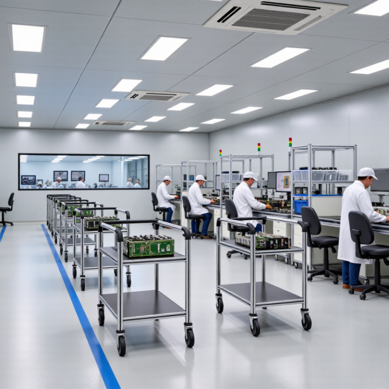
ESD safe flooring is a conductive or static-dissipative surface connected to a verified grounding system. It does not magically remove electricity. Instead, it controls charge movement through flooring, footwear, and personnel. The ESD Association reports that walking across carpet can generate approximately 35,000 volts. Some sensitive electronic devices may fail below 100 volts. The danger can be invisible.
ANSI/ESD S20.20-2021 and IEC 61340-5-1:2016 emphasize the complete person-footwear-flooring system. IEC guidance commonly uses a maximum resistance of 3.5 × 10⁷ ohms for personnel grounding paths. Flooring resistance is also evaluated, often below 1.0 × 10⁹ ohms, depending on the application. These values help discharge static gradually, without creating a sudden spark near exposed components.
Installation details matter. Copper grounding strips, conductive adhesives, clean footwear, and verified earth connections must work together.
In facility audits, dust and incorrect cleaning chemicals often increase surface resistance. That part is easy to overlook.
A floor may pass testing after installation, then drift outside specification months later. Routine resistance measurements, footwear checks, and documented maintenance provide stronger evidence than appearance alone. Without periodic testing, the claimed protection remains an assumption.
ESD safe flooring is used where a small static discharge can damage sensitive equipment. Semiconductor plants rely on it around assembly benches, inspection stations, and cleanroom entrances. A tiny spark may be invisible, yet it can weaken electronic components before testing reveals the fault. Flooring alone cannot solve every electrostatic problem. Grounding, footwear, humidity, and worker training must work together.
Medical facilities also use conductive or dissipative flooring in imaging rooms, laboratories, and device assembly areas. These spaces may contain monitors, sensors, and compact circuit boards. Data centers install ESD control flooring near server aisles and maintenance zones. The surface helps channel charge away when technicians move across raised floors. Regular resistance testing is essential. Dust and floor coatings can change performance over time.
Manufacturing sites use ESD safe flooring for robotics, control panels, battery systems, and precision instruments. Aerospace workshops and telecommunications laboratories may need similar protection. The correct flooring depends on traffic, cleaning methods, moisture, and the facility’s grounding design. A material that works well in a dry laboratory may perform poorly near washdown areas. That detail is easy to miss. Facility managers should document test results and inspect seams, connections, and worn sections. Standards can guide the process, but site conditions still require professional judgment. Mistakes happen, especially when teams treat flooring as a standalone solution.
ESD safe flooring helps control static electricity in electronics rooms, laboratories, clean manufacturing areas, and repair spaces. It works as part of a grounded system, guiding electrical charges away from sensitive equipment. This can reduce sudden discharges that damage circuit boards, sensors, and stored components. It may also reduce uncomfortable shocks for employees moving across dry floors.
The operational benefits are practical. A continuous, correctly installed surface creates fewer gaps than temporary mats. It can support smoother trolley movement and simpler daily cleaning. However, flooring is not a magic shield. Poor grounding, unsuitable footwear, or neglected testing can weaken protection. Facility teams should verify resistance values after installation and during routine maintenance. Records matter when investigating equipment failures.
Selecting the right ESD safe flooring begins with the room, not the color chart. In electronics assembly areas, I examine walking routes, workstations, carts, and exposed equipment. A floor can pass a laboratory test yet fail after poor installation. Measure electrical resistance across several points, including joints and edges. Request current test reports, installation records, and maintenance instructions. These documents reveal more than a sales promise.
The target resistance range should match your equipment, footwear, and grounding plan. Human movement matters too. Dry air and synthetic soles can change charge behavior.
Choose the construction according to daily loads. Conductive or dissipative systems may suit different risk levels, but verify the specification onsite. Consider forklifts, rolling chairs, dropped tools, cleaning chemicals, and moisture. A smooth resin surface is easy to clean, while resilient sheet flooring may simplify repairs. Neither is automatically best.
Check substrate moisture and flatness before installation. Small cracks can become expensive failures. Bonding must remain continuous and recorded, then tested after curing. I prefer independent verification before production starts. It catches uncomfortable details. A grounded floor may still perform poorly when footwear is unsuitable. Train staff, document periodic tests, and inspect high-traffic zones. I would question any system promising permanent performance without maintenance. That claim deserves scrutiny.
Why Choose ESD Safe Flooring for Your Facility?
Installation, Grounding, and Maintenance Requirements
ESD-safe flooring works only when the complete grounding system works. ANSI/ESD S20.20-2021 identifies controlled resistance as a core compliance requirement. Many conductive or dissipative floors target resistance-to-ground below 1.0 × 10⁹ ohms. However, the exact limit depends on the facility’s risk assessment and selected footwear system.
Installers should prepare a dry, level substrate before applying tiles, sheets, or coatings. Uneven areas can create weak bonds and hidden trip hazards. Copper grounding strips must connect to a verified grounding point, not simply to nearby metalwork. Testing should include point-to-point resistance, resistance-to-ground, and the footwear-floor system. ANSI/ESD STM97.1 commonly evaluates this combined system, with a 3.5 × 10⁷ ohm upper limit used in many controlled environments. A perfect floor reading can still mislead.
Tips: Test before occupancy. Record probe locations, humidity, cleaning products, and instrument calibration. IEC 61340-5-1:2016 also stresses documented verification and a controlled ESD program. Maintenance should remove dust and insulating residue without leaving waxy films. Use approved cleaners, inspect seams monthly, and retest after repairs or layout changes. High-traffic entrances deserve extra attention. That is where performance often drifts first. Frequencies should follow measured risk, not habit. Teams sometimes over-clean, then damage the surface. A written procedure helps, but review it when real conditions disagree.
Use an ESD-rated flooring system, install conductive adhesive where specified, and ensure seams and joints provide continuous electrical performance.
Connect the floor system to a verified protective earth or designated grounding point. Personnel grounding systems commonly use a 35 MΩ maximum resistance limit for current-limiting protection.
Keep the surface clean with ESD-compatible products and periodically verify resistance to ground, continuity, and grounding connections according to the site ESD control plan.
The logarithmic chart shows commonly referenced resistance boundaries used in ESD control: conductive materials are below 10⁴ Ω, dissipative materials are from 10⁴ Ω to below 10¹¹ Ω, ESD flooring systems are commonly evaluated against a 10⁹ Ω maximum resistance-to-ground limit, and personnel grounding systems commonly use a 3.5 × 10⁷ Ω maximum limit. Always verify the applicable project specification and current ESD standard.
„Thanks to the LUVIR technology, the solder resist process could be switched directly from the previously used mask exposure to direct exposure. As an outstanding digital solution on the market, this technology has been able to demonstrate fast process times and superior quality on our certified conventional ink in production. This allowed us to fully digitize the solder mask process at low cost – without process or ink adjustments. An excellent benefit to our production in Rot am See.“
Ralf Göhringer (Head of Production WE Rot am See)
I would definitely recommend the Limata machine and team for a future company purchase
Michael Greenaway
Compunetics Inc.
“The Limata ldi has been amazing!! Best thing we did was buy this machine”
Richard Brady
GM
Circuitlabs
“Since 2019, we have been running the Limata X1000 LDI system (including LUVIR for solder mask imaging) in daily production as an addition to our current process with film. The machine was capable of properly exposing Taiyo PSR-4000 BN (DI) solder mask types on normal to high-copper boards using a new and unique direct imaging process. The machine operating interface is very user friendly which allowed for a quick technical training curve. The pre-registration processing reduced several seconds of production time at every print. Limata support and service staff is incomparable. They supported our team every step of the way at basically any time of the day or night, with literally, an immediate response time, customizing the software interface to best fit our Operations and needs.
We have exposed more than 8,000 prints since end of October, on various solder mask colors and some resist film panels. Limata, has proven to be very capable and innovative. They are a strong contender in the industry.
We have very much enjoyed this project, and working with the team!
Thank you Limata for the continued support and being a part of our growth.”
Bill Sezate
Vice President, GM
Summit Interconnect
As a replacement to our current contact exposure process with film, the LIMATA X2000 system including LUVIR-Technology was capable of properly exposing non-LDI solder mask types using a direct imaging process. The machine offers cutting edge software with a very intuitive operating interface which allowed for quick technician training curve. The dual drawer system combined with pre-registration processing reduced several seconds of production time at every machine cycle. Limata support and service staff is world class. They added software patches to keep production running at shortest possible response times, customized the software interface to best fit our in-house Operations system, and even wrote a step-by-step machine processing manual. As a result of the project, we have exposed more than 16,000 times on various product types and solder mask brands/colors. Limata, in a very short timeframe as a company, has definitely shown they are truly innovative and will be challenging the industry of direct imaging for the top spot.
Kevin Beattie
Process Engineer
TTM Technologies
Forest Grove Division