A battery energy storage system is only as dependable as the connections between its components. A Bess Connector joins battery modules, racks, inverters, or other equipment, carrying current while maintaining a secure electrical and mechanical connection. The term covers several designs, not one universal plug. Small parts matter. A connector that fits poorly, handles too little current, or is difficult to install can create operational problems and complicate maintenance. The right choice depends on the system’s electrical requirements and physical layout.
This guide explains common BEss Connector types and the details to check before selecting one. These include rated voltage and current, conductor size, contact resistance, temperature range, ingress protection, locking method, and expected connection cycles. For example, a compact connector may suit a tightly arranged battery rack, while a different design may be easier to service where space is available. Check compatibility with the battery and inverter terminals; matching shapes alone do not establish electrical suitability. Fit matters. Installation instructions and manufacturer datasheets are essential references, particularly for torque, cable preparation, and environmental limits. Requirements can vary between systems, and a rating printed on one component does not automatically apply to the complete connection. This overview offers practical selection criteria, but it cannot replace engineering review of a specific installation. A little uncertainty is useful here: connector names can be inconsistent, so verify the exact part number and documented ratings before ordering.
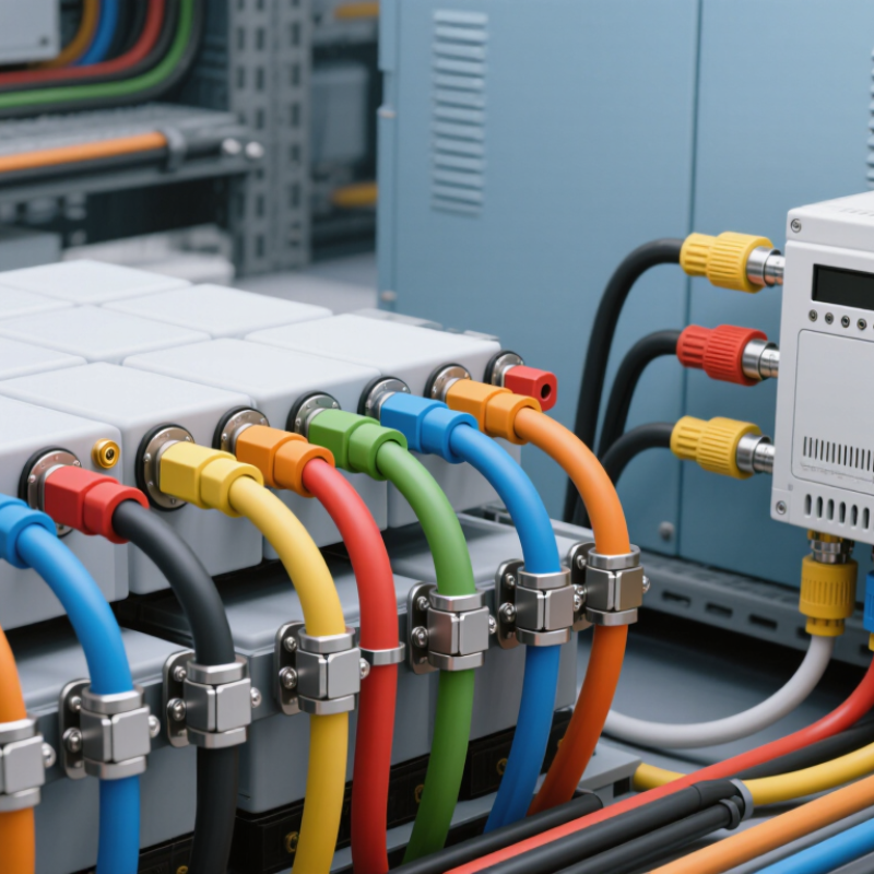
A BESS connector joins parts of a battery energy storage system while carrying power, signals, or both. Its job is more specific than simply making a secure connection. DC power contacts carry current between battery modules, racks, and conversion equipment. They need suitable voltage and current ratings, plus insulation that fits the installation. A poor match can create heat at the contact point. That small detail matters.
Signal contacts handle lower-power information, such as temperature readings, status, or control commands. They may use separate pins or a dedicated connector from the main DC path. Ground connections provide a deliberate path for fault current and help bond conductive enclosures. Do not assume a signal reference and protective ground are interchangeable. In practice, wiring diagrams can be untidy, and connector labels alone may not reveal the intended path. Check the equipment documentation and confirm pin assignments before selecting or mating parts.
Tips: Match the connector to the cable size, operating current, voltage, temperature, and enclosure conditions. Check keying and contact arrangement, too. For grounding, verify the specified bonding point and conductor size. If the design documents disagree, pause and get qualified technical review; guessing is not a good test method.
A BESS connector is an electrical interface that carries energy between parts of a battery energy storage system. At cell level, connections often use welded tabs or busbars, not plug-in connectors. Between modules, flexible links or bolted busbars accommodate small shifts and vibration. Rack connections usually need high-current DC connectors with clear polarity, secure locking, and protection against accidental contact. Small details matter. A handle that feels loose during installation deserves attention, even when the electrical rating looks suitable.
Follow the path outward. Rack outputs connect to the power conversion system, or PCS, through DC cables and terminals rated for the system’s voltage and current. The PCS converts power for the AC side, where separate cables and terminals lead toward transformers and the grid. DC and AC interfaces are not interchangeable. Check conductor size, fault-current capability, temperature range, enclosure protection, and mating compatibility at every boundary. During commissioning, verify polarity, specified torque, cable bend radius, and temperature under load. It is easy to focus on current ratings and overlook service access; that can make a sound connection awkward to inspect later. The right type depends on the exact location and system design, not just the battery’s capacity.
Compare Bolted, Busbar, and Pluggable Connector Designs
A BESS connector joins battery racks, inverters, or DC busbars while carrying high current. The choice affects installation, servicing, and heat management. The IEA’s 2024 Batteries and Secure Energy Transitions report says global energy storage capacity must grow sixfold by 2030, including around 1,200 GW of battery storage. That scale makes reliable connection design essential, not cosmetic.
Bolted connectors are familiar and mechanically robust. They suit fixed installations, but crews must follow specified torque values and inspect joints for loosening or corrosion. A neat drawing can still hide a hot joint.
Busbar connections use rigid conductors to link equipment compactly, often reducing cable clutter. They need accurate alignment, adequate spacing, and insulation suited to the system voltage.
Pluggable connectors can speed rack replacement and maintenance. Their convenience depends on verified current ratings, touch protection, mating-cycle limits, and secure locking.
Choose by continuous and peak current, temperature rise, fault withstand, enclosure conditions, and service access—not catalogue current alone. Check the rating for the actual conductor size and installation temperature. Small details matter. A connector that works well in a clean cabinet may struggle with vibration, dust, or repeated servicing; the design review should account for those conditions.
A BESS connector joins battery modules, racks, or power-conversion equipment while carrying high-voltage DC. For systems rated from 1,000 to 1,500 V DC, check the connector’s maximum DC voltage rating against the system’s highest operating voltage—not just its nominal voltage. Voltage comes first. DC arcs can persist, so use connectors specifically rated for DC service and the intended voltage range.
Size current for the actual circuit. Estimate maximum continuous current from power and the lowest expected operating voltage, then compare it with the connector’s rating. Check the cable size, ambient temperature, and installation conditions too; heat can reduce usable current. A connector rated for the right voltage may still be undersized for sustained load. Confirm the rating with technical data for the exact cable and assembly.
Tips: Leave sensible margin for temperature and future operating changes. Verify polarity, locking, and touch protection, and avoid mixing parts that are not specified to mate. A tidy calculation can miss a hot enclosure or tightly bundled cable. Field conditions matter, and they deserve a second look.
A BESS connector is a small part of a high-energy system, but a loose contact can create heat at the joint. UL 1973 evaluates batteries for stationary use; UL 9540 covers energy storage systems and equipment. IEC 62933 addresses electrical energy storage systems, including safety considerations for electrochemical systems. These standards do not make every connector interchangeable. Check how the connector is evaluated within the complete battery or system, and confirm its voltage, current, temperature, and fault-current ratings match the design. Small details matter.
The International Energy Agency’s 2024 report, Batteries and Secure Energy Transitions, says global energy storage capacity needs to grow sixfold by 2030, reaching about 1,500 GW; batteries provide nearly 1,200 GW of that total. More installations mean more connections to inspect and maintain. For a BESS, compare connector ratings with the actual operating current, cable size, enclosure conditions, and expected service work. Check for secure locking, clear polarity marking, and accessible inspection points. A connector may meet a component requirement yet still be unsuitable for a particular system. I would not treat a certificate as a substitute for checking the system’s test documentation and installation instructions. That distinction is easy to miss.
„Thanks to the LUVIR technology, the solder resist process could be switched directly from the previously used mask exposure to direct exposure. As an outstanding digital solution on the market, this technology has been able to demonstrate fast process times and superior quality on our certified conventional ink in production. This allowed us to fully digitize the solder mask process at low cost – without process or ink adjustments. An excellent benefit to our production in Rot am See.“
Ralf Göhringer (Head of Production WE Rot am See)
I would definitely recommend the Limata machine and team for a future company purchase
Michael Greenaway
Compunetics Inc.
“The Limata ldi has been amazing!! Best thing we did was buy this machine”
Richard Brady
GM
Circuitlabs
“Since 2019, we have been running the Limata X1000 LDI system (including LUVIR for solder mask imaging) in daily production as an addition to our current process with film. The machine was capable of properly exposing Taiyo PSR-4000 BN (DI) solder mask types on normal to high-copper boards using a new and unique direct imaging process. The machine operating interface is very user friendly which allowed for a quick technical training curve. The pre-registration processing reduced several seconds of production time at every print. Limata support and service staff is incomparable. They supported our team every step of the way at basically any time of the day or night, with literally, an immediate response time, customizing the software interface to best fit our Operations and needs.
We have exposed more than 8,000 prints since end of October, on various solder mask colors and some resist film panels. Limata, has proven to be very capable and innovative. They are a strong contender in the industry.
We have very much enjoyed this project, and working with the team!
Thank you Limata for the continued support and being a part of our growth.”
Bill Sezate
Vice President, GM
Summit Interconnect
As a replacement to our current contact exposure process with film, the LIMATA X2000 system including LUVIR-Technology was capable of properly exposing non-LDI solder mask types using a direct imaging process. The machine offers cutting edge software with a very intuitive operating interface which allowed for quick technician training curve. The dual drawer system combined with pre-registration processing reduced several seconds of production time at every machine cycle. Limata support and service staff is world class. They added software patches to keep production running at shortest possible response times, customized the software interface to best fit our in-house Operations system, and even wrote a step-by-step machine processing manual. As a result of the project, we have exposed more than 16,000 times on various product types and solder mask brands/colors. Limata, in a very short timeframe as a company, has definitely shown they are truly innovative and will be challenging the industry of direct imaging for the top spot.
Kevin Beattie
Process Engineer
TTM Technologies
Forest Grove Division
