A Blade Antenna For Uav can look like a simple part: a slim housing above a carbon-fiber airframe. Its performance, however, depends on frequency, polarization, mounting position, and the radio system around it. A compact blade may suit a fixed-wing platform, while a multirotor’s frame and wiring can distort its radiation pattern. Small installation choices matter.
The market is growing, but growth does not select the right antenna. Drone Industry Insights’ Drone Market Report 2024–2030 estimates a global drone market of $30.6 billion in 2024, potentially reaching $54.6 billion by 2030. That forecast signals expanding applications, not a universal antenna specification. Dr. Nuno Borges Carvalho, an IEEE Fellow whose research includes UAV communications, offers a useful paraphrased design takeaway: “Evaluate the antenna as part of the complete radio link, not as an isolated accessory.” This is not a verbatim published quotation. Readers should verify any specific antenna claim against the manufacturer’s datasheet and test results.
This guide examines gain, frequency coverage, polarization, weight, connector type, and environmental protection. It also considers where the antenna sits, and what nearby batteries or metal components may block. The best choice depends on the mission and installation, not just the product label. A detail is easy to miss: a strong datasheet cannot fix poor placement. Begin with the radio requirements, then compare antennas using measurable evidence.
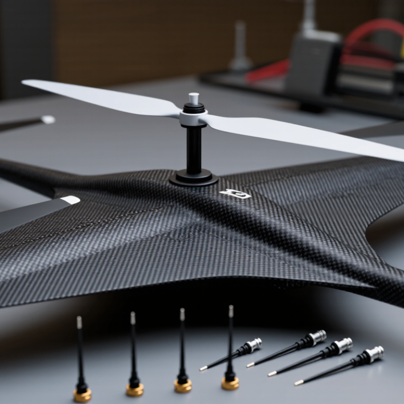
How to Choose the Best Blade Antenna for UAVs in 2026?
Understand the Role of Blade Antennas in UAV Systems
A blade antenna helps a UAV maintain radio links for command, telemetry, and other onboard communications. Its shape can reduce drag compared with taller exposed antennas, but aerodynamic form is only part of the decision. The antenna must suit the radio’s operating frequency and the airframe’s available mounting space. Small details matter.
Placement affects performance. Carbon-fiber structures, batteries, and wiring can obstruct or disturb radio signals, so an antenna mounted close to them may perform poorly. Keep it clear of conductive materials where practical, and check that its orientation matches the system’s polarization. Vibration and weather exposure also matter, especially during repeated outdoor flights. A neat installation is not necessarily an effective one.
Tips: Confirm frequency compatibility, mounting clearance, connector fit, and the antenna’s specified ground-plane requirements. Test link quality with the aircraft in several orientations, not just on a workbench. It is easy to focus on range claims and overlook installation conditions; that can lead to disappointing results. Record the setup and compare readings after changes.
Choose an antenna frequency that matches the radio system and its assigned operating band. A mismatch can reduce range and waste transmitter power. Check the antenna’s specified bandwidth, not just its center frequency. A UAV carrying separate control, telemetry, and navigation systems may need multiple antennas, carefully spaced to limit interference. Carbon-fiber frames, batteries, and wiring can also detune an antenna or block its signal. Measure performance on the finished airframe, not only on a workbench.
A blade’s placement matters as much as its datasheet. Keep it clear of conductive structures, and consider how the aircraft’s pitch and roll affect line of sight. For missions near ground stations, test at realistic heights and distances. Use a network analyzer to check the installed antenna across its operating band, then verify the link during controlled flight tests. A bench result can still mislead: vibration, cable routing, and nearby electronics may change real-world performance. Record the setup and results so later changes can be compared rather than guessed.
Choosing a blade antenna for a UAV means comparing gain, radiation pattern, and usable communication range—not just the largest number on a specification sheet. Gain describes how energy is distributed, not how much power the antenna creates. A higher-gain blade can concentrate coverage toward the horizon, but may provide less coverage above or below its main axis. That matters when a UAV banks, climbs, or changes heading.
Check the radiation pattern in the aircraft’s actual mounting position. A carbon-fiber frame, battery, wiring, or nearby metal can block or distort signals. Even a small shift in antenna angle may create a weak spot. Look for pattern data across the operating frequency, and confirm that the antenna’s polarization matches the rest of the link. Small details count.
Communication range depends on more than antenna gain. Transmit power, receiver sensitivity, cable loss, interference, and terrain all affect the link. A quoted range is not a promise. There is no perfect pick. Compare candidate antennas using the same radio setup, then test them at different headings and flight attitudes in a controlled, permitted area. Record signal strength and any dropouts. I would treat an uneven result as useful evidence, not a failed test; real installations rarely match an ideal diagram exactly.
A blade antenna for a UAV must fit the airframe, not just the frequency plan. Check the antenna’s full length and height against nearby propellers, landing gear, and payloads. Leave enough clearance to prevent contact during vibration or a hard landing. A compact unit may reduce drag, but its smaller size does not automatically mean better performance.
Include the cable and connector when checking total weight. Even a few grams can matter on a small aircraft, especially when the antenna sits far from the center of gravity. Mounting position also affects signal quality. Carbon-fiber structures can weaken radio signals, so test the intended location with the aircraft assembled. Check the specified temperature range, moisture protection, and UV resistance for your operating conditions. An IP rating applies only under defined test conditions; it is not a promise of unlimited weather protection. Real installations can be less tidy than drawings suggest.
Tips: Secure the cable with strain relief, and avoid sharp bends near the connector. Confirm the mount stays firm after repeated flights. If possible, compare signal readings in the planned orientation before final installation. A quick bench test helps, but it cannot replace an airborne check.
Choosing a blade antenna for a UAV starts with the airframe, not the catalogue. Check the antenna’s frequency range, impedance, connector, and polarization against the radio and cable. A mismatch can reduce link margin, even when the antenna looks suitable. Measure the mounting area and confirm the blade clears propellers, control surfaces, and landing gear throughout movement. Small gaps matter.
Validate regulations before installation. In 2026, permitted frequencies, transmit power, equipment approvals, and operating conditions can vary by country and flight category. Check current guidance from the relevant aviation and communications authorities; do not assume that a component approved in one market is acceptable everywhere. Keep the antenna’s documentation with the aircraft records. That saves time during reviews.
Then test it in flight conditions that reflect real use. A carbon-fiber fuselage, battery, wiring, or payload may shadow the signal, so placement deserves careful testing. Compare link quality at different headings and expected operating distances, and watch for dropouts during turns. A ground test helps, but it cannot reproduce every flight attitude. I have found that tidy installations can still perform poorly when the antenna sits too close to noisy electronics. That is an easy detail to miss. Recheck after changing payloads, cables, or mounting hardware, and record the results before relying on the setup.
„Thanks to the LUVIR technology, the solder resist process could be switched directly from the previously used mask exposure to direct exposure. As an outstanding digital solution on the market, this technology has been able to demonstrate fast process times and superior quality on our certified conventional ink in production. This allowed us to fully digitize the solder mask process at low cost – without process or ink adjustments. An excellent benefit to our production in Rot am See.“
Ralf Göhringer (Head of Production WE Rot am See)
I would definitely recommend the Limata machine and team for a future company purchase
Michael Greenaway
Compunetics Inc.
“The Limata ldi has been amazing!! Best thing we did was buy this machine”
Richard Brady
GM
Circuitlabs
“Since 2019, we have been running the Limata X1000 LDI system (including LUVIR for solder mask imaging) in daily production as an addition to our current process with film. The machine was capable of properly exposing Taiyo PSR-4000 BN (DI) solder mask types on normal to high-copper boards using a new and unique direct imaging process. The machine operating interface is very user friendly which allowed for a quick technical training curve. The pre-registration processing reduced several seconds of production time at every print. Limata support and service staff is incomparable. They supported our team every step of the way at basically any time of the day or night, with literally, an immediate response time, customizing the software interface to best fit our Operations and needs.
We have exposed more than 8,000 prints since end of October, on various solder mask colors and some resist film panels. Limata, has proven to be very capable and innovative. They are a strong contender in the industry.
We have very much enjoyed this project, and working with the team!
Thank you Limata for the continued support and being a part of our growth.”
Bill Sezate
Vice President, GM
Summit Interconnect
As a replacement to our current contact exposure process with film, the LIMATA X2000 system including LUVIR-Technology was capable of properly exposing non-LDI solder mask types using a direct imaging process. The machine offers cutting edge software with a very intuitive operating interface which allowed for quick technician training curve. The dual drawer system combined with pre-registration processing reduced several seconds of production time at every machine cycle. Limata support and service staff is world class. They added software patches to keep production running at shortest possible response times, customized the software interface to best fit our in-house Operations system, and even wrote a step-by-step machine processing manual. As a result of the project, we have exposed more than 16,000 times on various product types and solder mask brands/colors. Limata, in a very short timeframe as a company, has definitely shown they are truly innovative and will be challenging the industry of direct imaging for the top spot.
Kevin Beattie
Process Engineer
TTM Technologies
Forest Grove Division