Choosing the right Fm Transmitters in China requires more than comparing wattage and price. Global buyers must examine frequency stability, harmonic suppression, cooling design, remote monitoring, and after-sales support. A transmitter may look impressive in a showroom, yet fail inside a hot, dusty studio.
Grand View Research reports that the global radio broadcasting market reached approximately USD 40.8 billion in 2023. Its forecast also indicates steady growth through 2030. This expansion supports continued demand for reliable transmission equipment, especially in regional stations, community networks, and low-power broadcasting projects. However, market growth does not guarantee equal manufacturing quality.
Look closely.
The International Telecommunication Union emphasizes efficient spectrum use and responsible radio-frequency management. Therefore, buyers should request test reports covering output power, frequency accuracy, spurious emissions, and electromagnetic compatibility. These documents matter more than attractive product photographs.
Broadcast engineer John Bisset has described the transmitter as “the heart of the radio station.” That observation remains practical. When the transmitter overheats, even a carefully produced program can disappear within minutes. I have also seen buyers focus too heavily on purchase cost. That approach can overlook replacement parts, installation training, and technical response times.
The best Chinese Fm Transmitters are not automatically the cheapest models. They should match local licensing requirements, climate conditions, electrical standards, and coverage goals. Certification still needs verification. Supplier claims deserve testing.
This guide compares transmitter options for international buyers. It considers performance, compliance, serviceability, and long-term operating risk. Some conclusions may remain imperfect, because supplier specifications are not always measured under identical conditions. That limitation deserves attention.
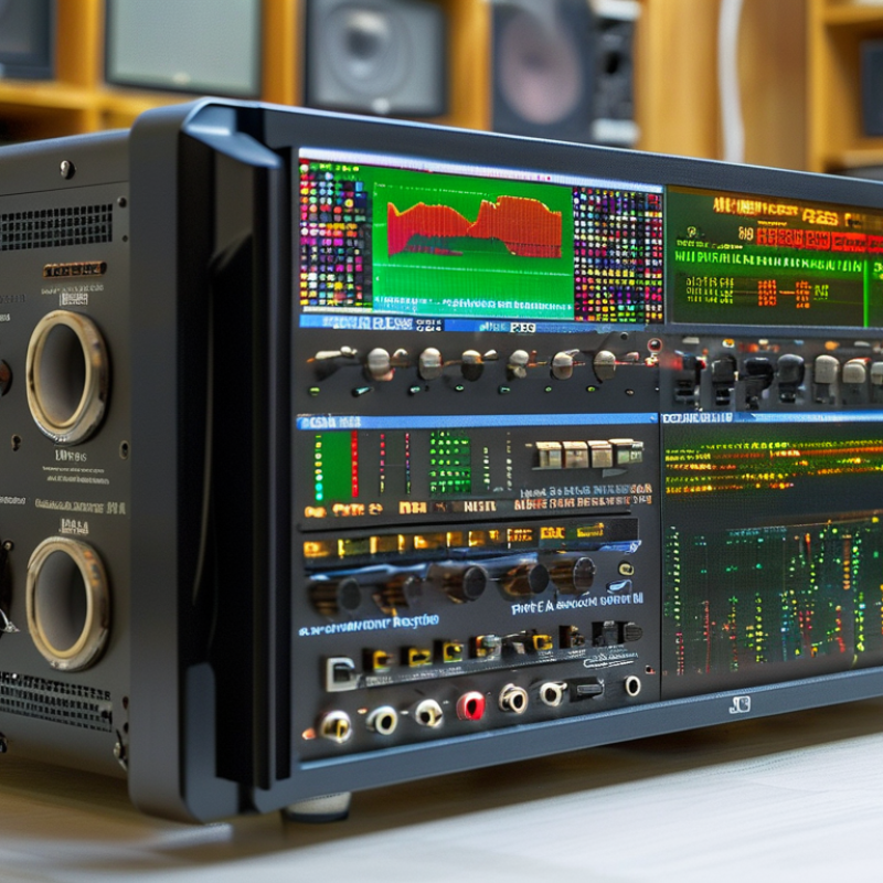
What Are the Best China FM Transmitters for Global Buyers?
Frequency coverage is the first practical question for international buyers. A transmitter marked 76–108 MHz appears flexible, but regional compatibility depends on its actual tuning range. Japan commonly uses 76–95 MHz, while many European markets use approximately 87.5–108 MHz. The United States and Canada generally operate within 88–108 MHz. China-market equipment may cover several regions, yet the displayed range does not guarantee legal operation everywhere.
Check the tuning step, frequency stability, and channel spacing before purchase. A 100 kHz step may suit one market but miss another channel plan. Fine adjustment, such as 50 kHz or smaller, can improve practical matching. Stable frequency control also matters. Even a small drift may create interference near crowded urban stations. During testing, compare the set frequency with a calibrated frequency counter, not only the front-panel display. Small screens can mislead.
Regional approval is equally important. Buyers should confirm permitted power, emissions, certification, and antenna requirements with the local communications authority. Low-power use may still require restrictions. Do not assume a broad-band transmitter is automatically universal. That assumption fails surprisingly often. A reliable supplier should provide a frequency chart, test data, operating manual, and clear model limitations. Ask whether the unit supports the target band natively. Software changes may not fix hardware limits. Some specifications also omit performance at the band edges, which deserves careful review.
Choosing a China-made FM transmitter starts with power, but power alone is not a buying strategy. A 1 W unit suits laboratory checks, short-range community projects, or low-power relay work where permitted. It is compact. At 10–50 W, buyers gain more practical coverage, but antenna height and terrain still matter. A 100 W transmitter can serve a larger local area when the antenna system is properly matched.
Transmitters from 100 W to 1 kW often balance coverage, energy use, and maintenance costs. Technicians should inspect cooling fans, protection circuits, harmonic filtering, and output stability. Above 1 kW, installation becomes more demanding. A 5 kW or 10 kW system may require stronger electrical service, controlled ventilation, larger coaxial components, and trained operators. More power means more heat.
Global buyers should match the output class with licensed frequency limits, site conditions, and local broadcasting rules. Ask for test reports, efficiency data, reflected-power protection, and clear service documentation. During acceptance testing, measure output power after the transmission line, not only at the amplifier display. I have seen installations lose significant power through undersized coaxial cable and poor connectors. That small detail matters. A 10 kW transmitter cannot compensate for a weak antenna system, and a lower-power unit may perform better when the entire signal chain is engineered carefully.
What Are the Best China FM Transmitters for Global Buyers?
For global buyers, coverage planning starts with ERP, not transmitter wattage alone. Effective radiated power combines transmitter output, cable losses, and antenna gain. A 10-watt transmitter with 3 dBd antenna gain and 2 dB feeder loss produces roughly 12.6 watts ERP. This figure assumes compatible measurements and a properly tuned antenna system. That result is only a planning input. Not a promise.
Terrain often changes the answer dramatically. An elevated site may cover distant valleys, while a nearby ridge can block the signal completely. Buildings, trees, soil moisture, and antenna height also affect FM reception. VHF signals usually travel best with clear line-of-sight paths. Flat farmland may provide a wider service area than a crowded urban district. My first estimates were too optimistic because I ignored a low ridge behind the transmitter site. The map looked open. It was not.
Reliable planning uses a terrain profile, antenna height, frequency, ERP, and receiver sensitivity. Engineers can model several radial directions, then check weak areas with real field measurements. A practical installation should include measured cable loss and an antenna pattern, rather than relying on catalogue gain alone. Keep the antenna clear of metal structures and verify the final operating parameters against local technical requirements. Small details matter. Even a few metres of extra height can improve the signal near a blocked road or settlement. Coverage predictions remain imperfect, so a pilot test with portable receivers is often worth the effort.
| Planning Scenario | FM Frequency | Transmitter Output | Antenna Gain | Estimated Feeder and Connector Loss | Calculated ERP | Antenna Height Above Average Ground | Terrain Profile | Approximate Radio Horizon | Indicative Reliable Planning Range | Coverage Planning Comment |
|---|---|---|---|---|---|---|---|---|---|---|
| Small Urban Service | 98 MHz | 100 W | 0 dBd | 1.5 dB | 71 W | 30 m | Dense buildings, frequent obstruction and multipath | Approximately 25 km | 5–8 km | Use a well-positioned antenna and expect buildings to reduce indoor reception. The ERP is intentionally modest for localized service. |
| Suburban Community Service | 100 MHz | 300 W | 3 dBd | 1.0 dB | 476 W | 60 m | Rolling terrain with moderate development | Approximately 32 km | 12–20 km | Higher antenna elevation usually improves coverage more consistently than adding transmitter power at a low site. |
| Flat Rural Service | 102 MHz | 1 kW | 6 dBd | 1.5 dB | 2.82 kW | 100 m | Open, flat ground with limited obstruction | Approximately 40 km | 25–40 km | Suitable for broad rural coverage when the antenna site has clear line of sight toward the target service area. |
| Hilly or Mountain-Edge Service | 95 MHz | 1 kW | 3 dBd | 1.5 dB | 1.41 kW | 80 m | Ridges, valleys and partial shadowing | Approximately 36 km | 10–20 km | Terrain blockage can dominate the result. Additional low-power fill-in sites may outperform a major power increase. |
| Coastal or Very Open Regional Service | 106 MHz | 5 kW | 6 dBd | 2.0 dB | 12.6 kW | 150 m | Open coastal plain with a clear antenna path | Approximately 48 km | 35–50 km | Large ERP and high antenna elevation support regional service, but local licensing limits and interference protection still apply. |
| Low-Power Event or Campus Service | 88 MHz | 10 W | 0 dBd | 1.0 dB | 7.9 W | 15 m | Compact site with buildings nearby | Approximately 18 km | 1–3 km | Designed for short-range coverage. The practical service area is normally determined by legal power limits, buildings and receiver location. |
For global buyers, a China FM transmitter should be judged by measured signal quality, not impressive packaging. The 19 kHz stereo pilot must remain stable, because drift can reduce stereo separation and create audible weakness near the receiver’s decoding threshold. A practical inspection should check pilot frequency, injection level, audio distortion, and left-right channel separation.
Measure it carefully. A spectrum analyzer and calibrated FM receiver reveal problems that basic software may miss. Many professional systems target consistent pilot injection near 8–10 percent, while maintaining accurate 38 kHz stereo subcarrier phase.
Small drift matters. Poor shielding can also introduce hum, spurious signals, or unstable output during long operation. Heat testing is useful, although real installation conditions are often less controlled than laboratory tests.
RDS or RBDS support adds another quality layer. The 57 kHz data subcarrier should carry station identification, program information, and traffic data without repeated decoding errors. Buyers should verify selectable data rates, encoder compatibility, and performance at different modulation levels.
A clean display is not enough; test receivers several meters away and near the coverage edge. That matters. Specifications can look precise while firmware remains inconsistent.
I would request test records, sample-based inspection, and technical support before purchase. The transmitter must also meet the destination market’s frequency, power, emissions, and certification requirements. Availability and legal operation differ by country.
What Are the Best China FM Transmitters for Global Buyers?
A suitable FM transmitter must satisfy the destination country’s radio rules, not only its advertised power rating. In the United States, buyers should verify FCC authorization, operating frequency, field strength, occupied bandwidth, and unwanted emissions. A low-power unit still needs careful review. Its antenna, cable, and enclosure can change measured output.
For European markets, CE marking should be supported by a proper Declaration of Conformity and technical documentation. The Radio Equipment Directive usually involves spectrum use, electromagnetic compatibility, and electrical safety. Check the exact frequency band. A transmitter approved for one European region may not fit every national allocation or usage condition. Test results should identify the tested configuration, including antenna type and maximum power.
The ITU provides international radio regulations and technical frameworks, but it does not replace national approval authorities. Global buyers should compare ITU guidance with local licensing rules before shipment. Ask for recent laboratory reports covering harmonics, spurious emissions, frequency stability, and EMC performance. Inspect the label, manual, power adapter, and serial records. Small details matter.
A report is not a passport.
In procurement checks, missing antenna data often creates uncertainty. That weakness deserves attention. It is tempting to trust a certificate alone, but certification scope can be narrower than the product listing. Keep compliance files, destination-specific settings, and supplier declarations together. Independent testing may still be wise when the transmitter will operate near sensitive communication systems.
This comparison shows the primary compliance scope for global FM transmitter buyers. FCC rules address U.S. radio-frequency emissions and equipment authorization, CE conformity covers applicable European Union product requirements such as EMC and radio equipment rules, while ITU recommendations support international spectrum allocation and broadcasting planning rather than acting as a product certification.
„Thanks to the LUVIR technology, the solder resist process could be switched directly from the previously used mask exposure to direct exposure. As an outstanding digital solution on the market, this technology has been able to demonstrate fast process times and superior quality on our certified conventional ink in production. This allowed us to fully digitize the solder mask process at low cost – without process or ink adjustments. An excellent benefit to our production in Rot am See.“
Ralf Göhringer (Head of Production WE Rot am See)
I would definitely recommend the Limata machine and team for a future company purchase
Michael Greenaway
Compunetics Inc.
“The Limata ldi has been amazing!! Best thing we did was buy this machine”
Richard Brady
GM
Circuitlabs
“Since 2019, we have been running the Limata X1000 LDI system (including LUVIR for solder mask imaging) in daily production as an addition to our current process with film. The machine was capable of properly exposing Taiyo PSR-4000 BN (DI) solder mask types on normal to high-copper boards using a new and unique direct imaging process. The machine operating interface is very user friendly which allowed for a quick technical training curve. The pre-registration processing reduced several seconds of production time at every print. Limata support and service staff is incomparable. They supported our team every step of the way at basically any time of the day or night, with literally, an immediate response time, customizing the software interface to best fit our Operations and needs.
We have exposed more than 8,000 prints since end of October, on various solder mask colors and some resist film panels. Limata, has proven to be very capable and innovative. They are a strong contender in the industry.
We have very much enjoyed this project, and working with the team!
Thank you Limata for the continued support and being a part of our growth.”
Bill Sezate
Vice President, GM
Summit Interconnect
As a replacement to our current contact exposure process with film, the LIMATA X2000 system including LUVIR-Technology was capable of properly exposing non-LDI solder mask types using a direct imaging process. The machine offers cutting edge software with a very intuitive operating interface which allowed for quick technician training curve. The dual drawer system combined with pre-registration processing reduced several seconds of production time at every machine cycle. Limata support and service staff is world class. They added software patches to keep production running at shortest possible response times, customized the software interface to best fit our in-house Operations system, and even wrote a step-by-step machine processing manual. As a result of the project, we have exposed more than 16,000 times on various product types and solder mask brands/colors. Limata, in a very short timeframe as a company, has definitely shown they are truly innovative and will be challenging the industry of direct imaging for the top spot.
Kevin Beattie
Process Engineer
TTM Technologies
Forest Grove Division