As optical networks move toward higher bandwidth and tighter integration, CPO/NPO FAU suppliers face a practical challenge: connecting dense optical engines with reliable fiber interfaces. A fiber array unit may look small on a drawing. In a real package, alignment tolerances, end-face quality, and assembly repeatability can determine whether the link performs as expected. Tiny parts. Large consequences.
This guide compares seven suppliers for global buyers evaluating CPO/NPO FAU capability. It considers more than product claims. Buyers should examine fiber-count options, pitch and geometry control, polishing consistency, inspection methods, customization support, and production capacity. Ask how suppliers manage alignment across batches. Request sample measurements, not only catalog specifications. A polished datasheet is useful, but it cannot show every production weakness.
Professor John Bowers is a prominent researcher in silicon photonics and integrated photonics. To avoid presenting an unsourced sentence as his verbatim quotation, this guide uses an editorial principle inspired by systems-level photonics research: “A successful optical package depends on the full interface, not one component alone.” That distinction matters when comparing suppliers. CPO/NPO FAU performance depends on the relationship between the array, optical engine, package design, and assembly process. Still, supplier comparisons have limits. Public information rarely reveals yield, long-term stability, or the real effort required for customization. Buyers should validate those points directly, with documented samples and clear acceptance criteria. No shortlist can replace that work.
CPO means co-packaged optics: optical engines sit in the same package as a switch or processor ASIC. Short electrical paths can reduce signal loss and power demand at high data rates. The trade-off is tighter thermal and service planning. Heat from nearby electronics can affect optical components, and replacing a failed engine may be harder than swapping a front-panel module.
NPO, or near-packaged optics, places optical engines close to the ASIC but outside its package. This keeps electrical connections short while allowing more separation between optics and hot silicon. It can make access easier, though the exact layout varies by system. They are not synonyms. Buyers should check measured link performance, cooling requirements, and repair procedures rather than relying on labels alone.
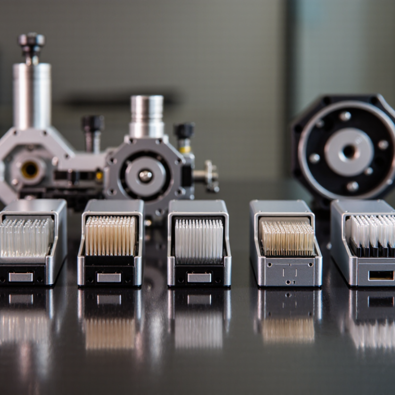
FAU means fiber array unit. It holds multiple fiber ends at a precise spacing and aligns them with optical ports on an engine or photonic chip. Alignment matters. Even a small offset, imperfect polish, or unstable bond can increase insertion loss. A neat diagram can hide these manufacturing details; that is easy to overlook. Ask for alignment tolerances, loss data, and reliability results under temperature cycling. CPO and NPO describe system placement, while an FAU is a fiber-coupling component used within optical assemblies.
CPO, NPO, and FAU describe different parts of an optical system, so buyers should not compare them as equivalent products.
Co-packaged optics places optical engines close to a switch ASIC, often within the same package. Shorter electrical paths can support higher bandwidth and lower signal loss. However, heat management and repairs may be more challenging because optical and electronic components sit close together.
Near-packaged optics positions optical engines near the ASIC, but generally keeps them outside its package. This can offer a balance between short signal paths and easier module access. Exact definitions vary across suppliers, so check diagrams and interface specifications rather than relying on labels alone.
FAU means fiber array unit. It holds multiple fibers at fixed spacing and aligns them with an optical chip or connector. It is a passive alignment component, not a switching technology. Small tolerances matter.
Tips: Ask for fiber pitch, channel count, insertion-loss data, and alignment tolerances. Confirm whether testing includes the complete optical path. I would not assume that two similarly named assemblies fit the same system; connector details can change compatibility. Inspect sample test reports, and clarify how suppliers handle cleaning and alignment checks.
For CPO, NPO, and FAU sourcing, compare suppliers on more than price and stated bandwidth. Check the optical engine’s lane count, wavelength plan, connector interface, and thermal limits against your system design. Ask for measured insertion loss, return loss, alignment tolerance, and test conditions. A result without its test setup is hard to compare. Request traceable lot records and a clear process for handling failed units.
Manufacturing readiness matters. Ask how suppliers control fiber-array alignment, epoxy cure, cleanliness, and inspection at each production stage. Review sample yield, capacity plans, lead times, and change-control procedures. The IEA’s Electricity 2024 report estimates that global data-center electricity use could reach 620–1,050 TWh in 2026. That range makes power efficiency a practical screening criterion, not just a marketing claim. Request measured power data under your expected operating conditions. A polished datasheet is not enough.
Tips: Start with a small pilot lot. Test optical loss, thermal behavior, and assembly repeatability using your own fixtures. Compare results across multiple samples and production lots. Some suppliers may not yet have long-term field data; note that gap, and agree on qualification milestones before scaling.
For global buyers, the right CPO, NPO, or FAU supplier depends on the required grade, destination, and delivery schedule. Useful options include integrated producers with traceable mill records, refiners that can provide consistent batch specifications, and regional aggregators serving smaller orders. Export-focused traders may coordinate freight and documents, while specialty processors can handle tighter quality requirements. Local distributors offer shorter lead times, and established bulk suppliers may suit recurring contracts. These are different supplier profiles, not automatic guarantees of quality.
Ask each candidate for a recent certificate of analysis, product specification, origin details, and a sample linked to the quoted batch. Confirm packaging, shipment terms, minimum volume, and how quality claims are handled. CPO, NPO, and FAU labels can vary across markets, so request the full product name and measurable parameters before comparing prices. Details matter. A low quote can conceal different moisture limits, delivery conditions, or testing methods. Check whether documents match the actual shipment, and speak with buyers who have received similar products. No checklist catches everything; even careful teams sometimes overlook a small mismatch in terminology. Keep written records of agreed tolerances and delivery dates.
| Supplier Profile | Primary Offering | Typical Application | Key Evaluation Dimensions | Buyer Due-Diligence Questions |
|---|---|---|---|---|
| 1. CPO Optical-Engine Integrator | Optical engines and integration support for co-packaged optics (CPO), where optical components are packaged alongside a switching or computing ASIC. | High-bandwidth, short-reach links in data-center and high-performance computing systems. | Electrical and optical interfaces, thermal design, fiber attachment, serviceability, and integration readiness. | Which host platforms and optical interfaces are supported? What system-level test and repair processes are available? |
| 2. NPO Optical-Module Supplier | Optical modules or engines designed for near-packaged optics (NPO), positioned close to the host ASIC while remaining a separate package. | Switch and accelerator platforms seeking short electrical paths between the ASIC and optical engine. | Package footprint, host electrical interface, optical lane configuration, thermal requirements, and maintainability. | Is the design compatible with the intended host board and cooling approach? Are interface specifications and qualification results available? |
| 3. Fiber Array Unit (FAU) Manufacturer | Precision fiber array units that hold and align multiple optical fibers for coupling to photonic devices or optical engines. | Fiber-to-chip coupling, photonic packaging, and optical-engine assembly. | Fiber count and pitch, fiber type, end-face geometry, alignment tolerances, and inspection method. | Can the FAU match the device layout and specified fiber type? What dimensional and end-face inspection data accompany each lot? |
| 4. Fiber-Attachment and Alignment Specialist | Active or passive alignment, fiber attachment, and optical coupling processes for photonic packages. | Prototype development and production assembly of PICs, optical engines, and FAU-equipped modules. | Alignment method, coupling-loss measurement, adhesive or bonding process, throughput, and repeatability. | How is coupling performance measured and recorded? Can the process support the required production volume and rework policy? |
| 5. Photonic Packaging and Assembly Provider | Packaging, assembly, and test services for photonic integrated circuits and optical subassemblies. | Engineering builds and manufacturing programs requiring optical, electrical, and mechanical integration. | Process control, package design support, environmental testing, traceability, and production capacity. | Which assembly and test steps are performed in-house? Can process records and lot traceability be provided? |
| 6. Precision Ferrule and Connector Supplier | Fiber ferrules, connectorized arrays, and related precision alignment components used in optical interconnects. | FAU interfaces, optical backplanes, and fiber connectivity for systems and modules. | Connector format, fiber compatibility, dimensional tolerances, end-face quality, and mating-cycle requirements. | Does the connector format match the system interface? What inspection criteria and cleaning guidance are supplied? |
| 7. Optical Test and Qualification Partner | Optical and electrical characterization services for FAUs, optical engines, and CPO/NPO assemblies. | Supplier qualification, production screening, failure analysis, and design verification. | Measurement capability, test coverage, calibration, data format, environmental conditions, and reporting turnaround. | Are test methods aligned with the product specification? Can raw data, calibration status, and failure-analysis reports be shared? |
Note: These are supplier capability profiles, not named companies. Product specifications, qualification status, capacity, and lead times vary by supplier and should be confirmed directly against the buyer’s requirements.
Comparing CPO, NPO, and FAU suppliers starts with the parts your design actually needs. Check whether a supplier provides optical engines, package-level integration, fiber array units, or only selected components. For FAUs, compare channel count, fiber type, pitch, end-face finish, and alignment tolerances. For CPO and NPO, ask about interface compatibility, thermal constraints, and assembly support. Details matter.
Request current data sheets and sample measurements, then compare them against your own acceptance criteria. A prototype result may not represent repeatability across production batches. Ask how tolerances are inspected and documented, and whether test reports include insertion loss and channel uniformity where relevant. Some suppliers may have strong products but limited application engineering; that trade-off deserves a direct conversation.
Market reach involves more than a list of destination countries. Check production capacity, typical lead times, regional technical support, and how clearly the supplier communicates shipping and service arrangements. Ask whether they can support pilot builds as well as larger orders, since scaling can expose gaps in process control. Maps can mislead. A broad sales network does not guarantee quick engineering help, and a smaller supplier may respond faster but have less spare capacity. Compare evidence, not just claims.
„Thanks to the LUVIR technology, the solder resist process could be switched directly from the previously used mask exposure to direct exposure. As an outstanding digital solution on the market, this technology has been able to demonstrate fast process times and superior quality on our certified conventional ink in production. This allowed us to fully digitize the solder mask process at low cost – without process or ink adjustments. An excellent benefit to our production in Rot am See.“
Ralf Göhringer (Head of Production WE Rot am See)
I would definitely recommend the Limata machine and team for a future company purchase
Michael Greenaway
Compunetics Inc.
“The Limata ldi has been amazing!! Best thing we did was buy this machine”
Richard Brady
GM
Circuitlabs
“Since 2019, we have been running the Limata X1000 LDI system (including LUVIR for solder mask imaging) in daily production as an addition to our current process with film. The machine was capable of properly exposing Taiyo PSR-4000 BN (DI) solder mask types on normal to high-copper boards using a new and unique direct imaging process. The machine operating interface is very user friendly which allowed for a quick technical training curve. The pre-registration processing reduced several seconds of production time at every print. Limata support and service staff is incomparable. They supported our team every step of the way at basically any time of the day or night, with literally, an immediate response time, customizing the software interface to best fit our Operations and needs.
We have exposed more than 8,000 prints since end of October, on various solder mask colors and some resist film panels. Limata, has proven to be very capable and innovative. They are a strong contender in the industry.
We have very much enjoyed this project, and working with the team!
Thank you Limata for the continued support and being a part of our growth.”
Bill Sezate
Vice President, GM
Summit Interconnect
As a replacement to our current contact exposure process with film, the LIMATA X2000 system including LUVIR-Technology was capable of properly exposing non-LDI solder mask types using a direct imaging process. The machine offers cutting edge software with a very intuitive operating interface which allowed for quick technician training curve. The dual drawer system combined with pre-registration processing reduced several seconds of production time at every machine cycle. Limata support and service staff is world class. They added software patches to keep production running at shortest possible response times, customized the software interface to best fit our in-house Operations system, and even wrote a step-by-step machine processing manual. As a result of the project, we have exposed more than 16,000 times on various product types and solder mask brands/colors. Limata, in a very short timeframe as a company, has definitely shown they are truly innovative and will be challenging the industry of direct imaging for the top spot.
Kevin Beattie
Process Engineer
TTM Technologies
Forest Grove Division