Choosing the best Industrial EMC Solution for 2026 starts with the equipment, not a product catalogue. A variable-frequency drive beside a long motor cable creates different interference problems from a compact control panel. The right approach depends on conducted emissions, radiated emissions, immunity, installation conditions, and the tests the finished system must pass. Small details matter. Cable routing, enclosure seams, connector backshells, and bonding points can change measured performance.
EMC engineer Henry W. Ott is associated with a useful principle: “Ground is a circuit concept, not an absolute concept.” That idea matters on real factory floors, where a painted panel, a long bonding lead, or a poorly terminated shield can undermine an otherwise sound design. An effective Industrial EMC Solution may combine filtering, shielding, grounding and bonding, surge protection, and careful layout. But no single combination works everywhere. A filter chosen without checking load current or frequency range may create new problems rather than solve the original one.
This guide examines how to assess solutions for 2026, compare design options, and verify performance through testing. It also considers practical constraints, including retrofit space, heat, maintenance access, and downtime. Check the applicable standards for the target market and product category; requirements can differ. Field experience helps, but it does not replace measured evidence. And even a careful design may need revision after testing. That is worth acknowledging.
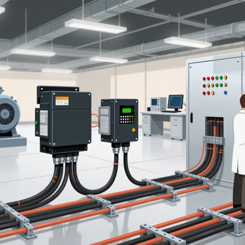
Industrial electromagnetic compatibility (EMC) means equipment can operate reliably without disrupting nearby devices. It also means it can tolerate electrical noise from its surroundings. In a factory, that noise may come from motor drives, switching power supplies, or long cable runs. A sensor may give unstable readings when a cable passes beside a high-current line. Small disturbances matter.
A practical EMC solution starts with the whole system, not one component. Engineers consider emissions, immunity, enclosure design, cable routing, grounding, and filtering together. For example, separating signal cables from motor cables can reduce unwanted coupling. Bonding metal panels carefully can help control interference paths. Testing under realistic operating conditions reveals issues that a quiet workshop may hide. The best fix is not always obvious; adding a filter can even affect performance if it is poorly selected.
Tips: Document cable routes and grounding points before troubleshooting. Test equipment while motors switch and loads change. Keep clear records, but revisit assumptions when results do not match expectations.
In 2026, industrial EMC requirements still depend on the equipment, installation environment, and markets where it will be used. The essential task is to identify the applicable standards and test limits before the design is fixed. A control cabinet on a factory floor may face different interference risks than a compact sensor near a motor drive.
Emissions and immunity both matter. Conducted and radiated emissions tests check whether equipment disrupts nearby systems. Immunity testing examines how it responds to electrostatic discharge, electrical fast transients, and surges. Small details matter. Cable length, shield termination, enclosure seams, and grounding can change test results. A filter selected from a schematic alone may not perform as expected once installed.
Testing should reflect real operating conditions, including switching loads and connected cables. Pre-compliance measurements can reveal problems early, but they do not replace formal testing against the relevant standard and edition. A passing result is useful, not magical. It can miss a weak setup or an untested operating mode. Document test configurations, failures, and design changes so results can be repeated and reviewed. There is rarely one fix for every product; practical EMC work often involves trade-offs that deserve another look.
Industrial EMC solutions control interference at its source, along its path, or at the equipment being protected. Shielded enclosures and conductive door gaskets reduce radiated emissions. Filters on power and signal lines suppress conducted noise, while cable shields and ferrites help manage interference on wiring. Grounding and bonding provide controlled paths for unwanted currents. Surge protection addresses transient events. No single measure fits every cabinet.
Selection should follow measured risks and installation conditions. IEC 61000-4-2 specifies electrostatic-discharge test levels of up to ±8 kV for contact discharge and ±15 kV for air discharge. These are test levels, not guarantees of field performance. A practical assessment checks emissions and immunity, then examines cable entry points, seams, grounding connections, and nearby drives. Real installations are messier than diagrams; even a small unbonded panel seam can undermine shielding.
Tips: Keep noisy power cables apart from sensor wiring, bond shield terminations with short, low-impedance connections, and verify fixes through testing. Document the test setup. Results can change when cable lengths or loads change.
The best industrial EMC solution for 2026 is not simply the one with the lowest test result. It must control emissions while remaining reliable around electrical noise from nearby equipment. Evaluate both sides of that task: what the system emits and what it can withstand.
Start with the real installation. Record cable lengths, grounding points, enclosure openings, and nearby drives or switching supplies. Test conducted and radiated emissions across relevant operating modes, including startup and heavy load. Then assess immunity to radio-frequency fields, electrostatic discharge, and fast electrical transients. Small details matter. A cable routed differently in the lab can change the result.
Compatibility deserves equal attention. Check that sensors, controllers, communication links, and safety functions keep working together during disturbances. Use representative cables and connected equipment, and document test conditions so results can be repeated. A clean bench result can feel reassuring, but it may not reflect a crowded factory floor. That gap is easy to underestimate. Some limits or test methods may also depend on the product and installation, so confirm the applicable requirements with a qualified test provider. Good EMC evaluation is measured, practical, and open to revision when field evidence disagrees.
Representative IEC RF immunity test frequency ranges are shown: IEC 61000-4-6 covers 150 kHz–80 MHz, and IEC 61000-4-3 covers 80 MHz–6 GHz. Frequency coverage alone does not determine compatibility; evaluate emissions and immunity against the applicable product requirements and installation environment.
What Is the Best Industrial EMC Solution for 2026?
Selecting an industrial EMC solution starts with the actual equipment and its surroundings. A motor drive beside a long sensor cable faces different interference risks than a compact control cabinet. List operating voltages, cable lengths, switching loads, enclosure materials, and nearby radio sources. Then define acceptable emissions and immunity using the standards that apply to the product and market. A filter alone is rarely the whole answer. Cable routing, bonding, shielding, and enclosure seams can matter just as much.
Tips: Test with real cables and representative loads. Check grounding connections and door seams. Keep a record of test conditions.
Validate the design in the configuration most likely to cause trouble: maximum load, active switching, and connected field wiring. Pre-compliance measurements can reveal noisy frequencies early, but they do not replace testing against applicable requirements. Change one feature at a time, such as ferrite placement or cable routing, and record the result. Small changes can shift a resonance. A tidy laboratory setup may also hide problems found on a factory floor, so include realistic installation details. No design is perfect on paper; revise it when measurements disagree with expectations.
„Thanks to the LUVIR technology, the solder resist process could be switched directly from the previously used mask exposure to direct exposure. As an outstanding digital solution on the market, this technology has been able to demonstrate fast process times and superior quality on our certified conventional ink in production. This allowed us to fully digitize the solder mask process at low cost – without process or ink adjustments. An excellent benefit to our production in Rot am See.“
Ralf Göhringer (Head of Production WE Rot am See)
I would definitely recommend the Limata machine and team for a future company purchase
Michael Greenaway
Compunetics Inc.
“The Limata ldi has been amazing!! Best thing we did was buy this machine”
Richard Brady
GM
Circuitlabs
“Since 2019, we have been running the Limata X1000 LDI system (including LUVIR for solder mask imaging) in daily production as an addition to our current process with film. The machine was capable of properly exposing Taiyo PSR-4000 BN (DI) solder mask types on normal to high-copper boards using a new and unique direct imaging process. The machine operating interface is very user friendly which allowed for a quick technical training curve. The pre-registration processing reduced several seconds of production time at every print. Limata support and service staff is incomparable. They supported our team every step of the way at basically any time of the day or night, with literally, an immediate response time, customizing the software interface to best fit our Operations and needs.
We have exposed more than 8,000 prints since end of October, on various solder mask colors and some resist film panels. Limata, has proven to be very capable and innovative. They are a strong contender in the industry.
We have very much enjoyed this project, and working with the team!
Thank you Limata for the continued support and being a part of our growth.”
Bill Sezate
Vice President, GM
Summit Interconnect
As a replacement to our current contact exposure process with film, the LIMATA X2000 system including LUVIR-Technology was capable of properly exposing non-LDI solder mask types using a direct imaging process. The machine offers cutting edge software with a very intuitive operating interface which allowed for quick technician training curve. The dual drawer system combined with pre-registration processing reduced several seconds of production time at every machine cycle. Limata support and service staff is world class. They added software patches to keep production running at shortest possible response times, customized the software interface to best fit our in-house Operations system, and even wrote a step-by-step machine processing manual. As a result of the project, we have exposed more than 16,000 times on various product types and solder mask brands/colors. Limata, in a very short timeframe as a company, has definitely shown they are truly innovative and will be challenging the industry of direct imaging for the top spot.
Kevin Beattie
Process Engineer
TTM Technologies
Forest Grove Division
