A Motor Threaded Shaft may look like a simple metal component, but its thread profile, straightness, surface finish, and material can affect assembly and service life. In a compact motor, a small pitch mismatch may cause binding or uneven movement. That matters. Buyers should also consider shaft diameter, lead, runout, hardness, coatings, and inspection methods. A broad catalog alone does not prove a supplier can meet a specific drawing. Nor is the lowest quote always the lowest-cost choice if parts need rework.
This guide to 10 Best Motor Threaded Shaft Manufacturers Worldwide offers a starting point for comparing potential suppliers, not a universal ranking. Manufacturing capabilities and service quality can vary by facility, material, order size, and application. Look for clear product information, custom machining options, documented quality controls, export experience, and responsive engineering support. Ask how dimensions are inspected and whether samples or inspection reports are available. Small checks help. Confirm published specifications against current datasheets and your own project drawings before placing an order. A supplier’s claims deserve careful review, especially when tolerances are tight or a shaft must fit an existing motor assembly. Even a useful shortlist has limits. The best choice depends on real operating conditions, and those details are sometimes incomplete at the start of a project.
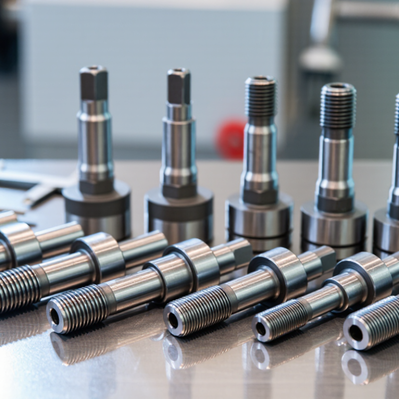
A motor threaded shaft combines a rotating motor output with external helical grooves. Those threads can secure a pulley, fan, coupler, or other component directly to the shaft. Paired with a compatible nut, they can also convert rotation into controlled linear movement. This function appears in compact actuators, feeders, adjustment mechanisms, and positioning equipment. Small details matter.
Thread pitch describes the distance between neighboring thread crests. A finer pitch generally moves a nut a shorter distance per revolution, while a coarser pitch can provide faster travel. The right choice depends on the required movement, load, speed, and available space. Shaft straightness and thread finish matter too. Poor alignment can cause vibration, uneven wear, or binding, even when the motor itself performs well.
A practical lesson is to check the full assembly, not just the shaft dimensions. Confirm thread direction, nut fit, mounting depth, and how the shaft will carry radial or axial forces. A shaft designed mainly to hold a component may not suit repeated linear loading. That distinction is easy to miss. Measurements also deserve a second look: a small mismatch in pitch or diameter can make installation difficult and shorten service life.
Choosing a motor threaded shaft manufacturer starts with fit, not price. Ask for drawings that define thread class, pitch diameter, runout, straightness, and shoulder location. Request inspection records from actual production batches, not only a polished sample. A dial indicator check can reveal shaft runout that may cause vibration after installation. Material certificates and heat-treatment records matter too, especially when shafts face repeated loads. ISO 286-1 provides a framework for dimensional tolerances, while thread gauges verify fit at the thread itself. One certificate alone proves little.
Production consistency depends on people as well as machines. The 2024 Deloitte–Manufacturing Institute workforce study estimates that up to 1.9 million U.S. manufacturing jobs could remain unfilled by 2033. That forecast is not shaft-specific, but it highlights why buyers should check operator training, inspection capacity, and backup processes. Ask how the supplier controls tool wear between batches. Request a first-article report, measurement methods, and lot traceability. A perfect sample is reassuring. Repeatability is harder. I would also compare response time for corrective actions; it is easy to overlook until a shipment fails inspection.
Tips: Send one representative drawing and ask for a sample inspection report before placing a large order. Confirm thread fit with a gauge, and check runout on the assembled shaft. Be cautious if tolerances are promised without a stated measurement method.
Leading motor threaded shaft manufacturers worldwide earn their place through repeatable accuracy, not catalogue size alone. Strong suppliers control thread pitch, concentricity, straightness, surface finish, and heat treatment across production runs. These details matter when a shaft must engage a nut smoothly and keep a small motor’s vibration low. The ten leading manufacturers should therefore be compared by process capability, inspection records, material traceability, and experience with the required shaft geometry—not by claimed rankings.
The International Energy Agency’s 2011 report, Energy-Efficiency Policy Opportunities for Electric Motor-Driven Systems, estimated that motor-driven systems used about 46% of global electricity. The estimate is older, but it shows why reliable motor components matter at scale. A shaft with inconsistent runout can increase noise, wear, and assembly rework. Ask suppliers for measured runout and thread-gauge results from production samples. A polished sample is not enough. I would also check how they handle design changes; this part is often overlooked.
Tips: Send a dimensioned drawing, annual volume, material grade, and operating conditions when requesting quotes. Ask for tolerances in writing, plus sample inspection data. Compare lead time and corrective-action support, not just unit price. One caveat: the “best” supplier depends on your motor design, and a shortlist may need revision after testing.
When comparing motor threaded shaft manufacturers, start with material suitability, not a catalog photograph. Carbon steel can offer strength and economical machining, while stainless steel may better resist moisture and cleaning chemicals. For compact motors, alloy choice affects weight, wear, and heat response. Ask how the supplier controls hardness and checks straightness; a shaft that looks smooth can still cause vibration. Small details matter. Request sample inspection data, including thread dimensions and runout measurements.
Production capability matters just as much. A manufacturer may handle turning and threading in-house, while another relies on outside processes that add time or variation. Ask about batch sizes, inspection frequency, and how tooling wear is tracked. Customization can include thread pitch, shaft length, stepped diameters, end features, and surface treatments. Clear drawings help, but tolerances should reflect the motor assembly rather than an arbitrary preference for tighter limits. I would not treat one polished sample as proof of consistent output; repeat parts tell a more useful story. Perfect documentation is not always available, so confirm what can be measured and reported before placing an order.
Motor threaded shafts convert rotation into controlled movement, making them useful wherever equipment must position, lift, or feed a component. In factory automation, they drive compact linear actuators on pick-and-place units and adjustable workstations. A shaft moving a sensor carriage only a few millimeters can help maintain repeatable inspection distances. Small details matter.
Packaging machinery uses threaded shafts to adjust guides, filling heads, and conveyor stops for different product sizes. In agriculture, they can operate seat adjustments, valve mechanisms, or positioning systems exposed to dust and vibration. These environments call for careful attention to thread wear, lubrication, and corrosion protection. A clean indoor test may not predict field performance.
Medical and laboratory equipment may use them in sample stages, adjustable beds, or instrument positioning assemblies, where smooth motion and manageable noise are important. HVAC systems and vehicle mechanisms also use threaded shafts for vents, seats, and other adjustable features. Engineers typically compare load, travel speed, duty cycle, and available space before choosing a design. The ideal choice is not always obvious. A finer thread can improve positioning, yet may move more slowly. That trade-off deserves testing in the actual assembly, because alignment and mounting stiffness can change how a shaft behaves.
Example screw configurations and their theoretical linear travel per motor revolution
Lead is the distance a threaded shaft advances in one revolution. For a uniform thread, lead equals pitch multiplied by the number of thread starts. These examples illustrate the relationship; actual shaft specifications depend on the selected design and application.
„Thanks to the LUVIR technology, the solder resist process could be switched directly from the previously used mask exposure to direct exposure. As an outstanding digital solution on the market, this technology has been able to demonstrate fast process times and superior quality on our certified conventional ink in production. This allowed us to fully digitize the solder mask process at low cost – without process or ink adjustments. An excellent benefit to our production in Rot am See.“
Ralf Göhringer (Head of Production WE Rot am See)
I would definitely recommend the Limata machine and team for a future company purchase
Michael Greenaway
Compunetics Inc.
“The Limata ldi has been amazing!! Best thing we did was buy this machine”
Richard Brady
GM
Circuitlabs
“Since 2019, we have been running the Limata X1000 LDI system (including LUVIR for solder mask imaging) in daily production as an addition to our current process with film. The machine was capable of properly exposing Taiyo PSR-4000 BN (DI) solder mask types on normal to high-copper boards using a new and unique direct imaging process. The machine operating interface is very user friendly which allowed for a quick technical training curve. The pre-registration processing reduced several seconds of production time at every print. Limata support and service staff is incomparable. They supported our team every step of the way at basically any time of the day or night, with literally, an immediate response time, customizing the software interface to best fit our Operations and needs.
We have exposed more than 8,000 prints since end of October, on various solder mask colors and some resist film panels. Limata, has proven to be very capable and innovative. They are a strong contender in the industry.
We have very much enjoyed this project, and working with the team!
Thank you Limata for the continued support and being a part of our growth.”
Bill Sezate
Vice President, GM
Summit Interconnect
As a replacement to our current contact exposure process with film, the LIMATA X2000 system including LUVIR-Technology was capable of properly exposing non-LDI solder mask types using a direct imaging process. The machine offers cutting edge software with a very intuitive operating interface which allowed for quick technician training curve. The dual drawer system combined with pre-registration processing reduced several seconds of production time at every machine cycle. Limata support and service staff is world class. They added software patches to keep production running at shortest possible response times, customized the software interface to best fit our in-house Operations system, and even wrote a step-by-step machine processing manual. As a result of the project, we have exposed more than 16,000 times on various product types and solder mask brands/colors. Limata, in a very short timeframe as a company, has definitely shown they are truly innovative and will be challenging the industry of direct imaging for the top spot.
Kevin Beattie
Process Engineer
TTM Technologies
Forest Grove Division
