Choosing the right Pneumatic Conveyor in 2026 means matching the system to the material, route, and production target—not chasing a single “best” machine. A fine powder behaves differently from fragile flakes or abrasive granules. A long overhead line also creates different pressure and maintenance demands than a short transfer between nearby vessels.
David Mills, a recognized author on pneumatic conveying, emphasizes design grounded in material behavior and operating conditions. The following is a paraphrased principle, not a verbatim quotation: “Start with the product and the process; then choose the conveying method.” That distinction matters. An undersized line can struggle to meet throughput, while excessive air velocity may increase wear or damage delicate materials. Real performance depends on testing, sound engineering, and honest operating data.
Details count. A buyer should check conveying distance, required capacity, air supply, filtration, controls, and access for cleaning. Ask suppliers how they handle bends, pressure loss, dust collection, and material changes. Request references from facilities moving similar products, not just impressive catalog figures. And inspect the assumptions behind every quote.
There is no universal winner.
This guide compares leading systems for industrial buyers, including dilute-phase and dense-phase options, typical applications, and practical trade-offs. It also flags questions worth asking before purchase. Some recommendations may change after a material test or site survey. That is not a flaw in the process; it is a reminder that dependable selection starts with evidence, not a ranking alone.
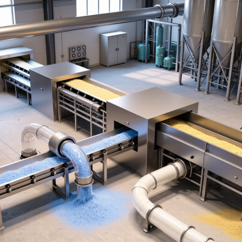
Pneumatic conveyor systems move bulk materials through enclosed pipes by using air pressure or vacuum. Air does the carrying. A blower pushes material toward a receiver, or a vacuum source draws it along the line. At the feed point, a rotary valve or other metering device controls how much material enters. At the destination, a filter separates powder from conveying air.
In dilute-phase conveying, particles travel quickly while suspended in the airflow. This approach can suit many free-flowing powders and granules, though fragile particles may break against pipe walls. Dense-phase systems move material more slowly in plugs or compact slugs. They can reduce particle damage, but need careful control of air, pressure, and feed rate. The right method depends on particle size, moisture, bulk density, and how the material behaves.
Pipe bends, long runs, and uneven feeding can change system performance. A powder that flows well in a test may bridge at a hopper outlet on a damp shift. That detail is easy to miss. Operators should watch pressure readings, filter loading, and material flow during startup and routine production. A practical layout is rarely as tidy as a drawing; maintenance access and cleaning needs matter too. Slightly imperfect assumptions at the design stage can become frequent stoppages later.
Pneumatic Conveying Systems are commonly classified by material concentration and airflow.Dilute-phase systems suspend particles in fast-moving air, making them suitable for powders and granules such as flour or plastic pellets.
Dense-phase systems move larger quantities at lower speeds, often in short pulses. They can reduce particle wear, but cohesive materials may still block bends or discharge points. Test the actual material.
Vacuum systems draw material toward a receiver, while pressure systems push it from a feed point to one or more destinations.
Vacuum conveying often suits enclosed pickup from bags or bins; pressure conveying can serve longer routes or multiple drops. These methods can operate in either phase.
The U.S. Department of Energy’s Improving Compressed Air System Performance sourcebook reports that leaks can waste 20–30% of compressed air in many plants. That figure is not specific to conveying lines, but it makes leak checks and airflow measurement practical buying criteria.
Dust matters. Before choosing a system, assess particle size, moisture, bulk density, route length, and cleaning needs.
A common mistake is choosing from capacity alone; real materials behave less neatly than catalog samples.
Selecting a pneumatic conveyor in 2026 starts with the material, not the equipment catalogue. Record particle size, bulk density, moisture, abrasiveness, and required throughput. A damp powder may cling to bends; fragile granules may break under high air velocity. The U.S. Department of Energy’s Improving Compressed Air System Performance: A Sourcebook for Industry estimates compressed air uses about 10% of electricity in U.S. manufacturing. That makes pressure, distance, and operating hours important cost factors. Small leaks matter.
Compare dilute-phase and dense-phase conveying against the material’s behavior and the route layout. Count elbows, vertical lifts, and likely cleanout points. DOE’s Energy Tips: Minimize Compressed Air Leaks reports that leaks can waste 20–30% of compressor output in poorly maintained systems. Include leak checks and filtration in lifecycle estimates, not just the purchase price. Test the powder. A short pilot run can reveal buildup or breakage that a spreadsheet misses. It is easy to underestimate changeover time, too. Ask suppliers for measured airflow, pressure, and product condition under representative operating conditions, then verify those figures during commissioning.
For 2026 purchasing decisions, compare pneumatic conveyor systems by operating performance, not headline capacity alone. Dilute-phase systems move material quickly through airflow, but higher velocities can increase pipe wear and particle breakage. Dense-phase systems use slower movement and higher pressure, which may suit fragile or abrasive products. They can also require more careful setup. Real results depend on the material, route, and feed consistency.
Tips: Test your actual material. Check moisture, particle size, bulk density, and friability. A short trial can reveal plugging or dust issues that a brochure may miss.
Compare total operating costs across the expected service life. Include compressor power, filters, valves, replacement bends, and maintenance access—not just purchase price. Ask suppliers to state the assumptions behind quoted throughput, such as pipe length and number of elbows. Then verify performance under conditions close to your plant’s. Material compatibility is easy to underestimate; a powder that flows well when dry may bridge after humidity rises. I would leave room for uncertainty in early estimates. Operators often discover small handling quirks only after installation, and those details matter.
A pneumatic conveyor performs only as well as its installation allows. Before assembly, confirm the material’s bulk density, moisture, particle size, and tendency to break or cling. These properties affect line diameter, air demand, and conveying mode.
A layout drawing should show pipe routes, bends, cleanout points, filters, and access for inspection. Keep bends gradual where possible; tight turns can increase wear and create stubborn buildup. Support long pipe runs securely, and seal joints carefully. Small details matter. Verify electrical connections, grounding, and dust-control provisions against the equipment instructions and site requirements before startup.
During operation, establish a baseline using pressure readings, airflow, motor load, and throughput. Change one setting at a time, then note the result. Sudden pressure changes, unusual noise, or falling output may signal a blockage, leak, worn elbow, or filter loading.
Stop and isolate equipment before opening lines or inspecting moving parts. Maintenance should include scheduled checks of seals, hoses, filters, rotary valves, and pipe wear, with findings recorded for trend comparisons. Cleaning intervals depend on the material and duty cycle; a calendar alone can miss early problems. Not always. Operators may need to revise the schedule after observing real buildup, especially at low points and bends.
„Thanks to the LUVIR technology, the solder resist process could be switched directly from the previously used mask exposure to direct exposure. As an outstanding digital solution on the market, this technology has been able to demonstrate fast process times and superior quality on our certified conventional ink in production. This allowed us to fully digitize the solder mask process at low cost – without process or ink adjustments. An excellent benefit to our production in Rot am See.“
Ralf Göhringer (Head of Production WE Rot am See)
I would definitely recommend the Limata machine and team for a future company purchase
Michael Greenaway
Compunetics Inc.
“The Limata ldi has been amazing!! Best thing we did was buy this machine”
Richard Brady
GM
Circuitlabs
“Since 2019, we have been running the Limata X1000 LDI system (including LUVIR for solder mask imaging) in daily production as an addition to our current process with film. The machine was capable of properly exposing Taiyo PSR-4000 BN (DI) solder mask types on normal to high-copper boards using a new and unique direct imaging process. The machine operating interface is very user friendly which allowed for a quick technical training curve. The pre-registration processing reduced several seconds of production time at every print. Limata support and service staff is incomparable. They supported our team every step of the way at basically any time of the day or night, with literally, an immediate response time, customizing the software interface to best fit our Operations and needs.
We have exposed more than 8,000 prints since end of October, on various solder mask colors and some resist film panels. Limata, has proven to be very capable and innovative. They are a strong contender in the industry.
We have very much enjoyed this project, and working with the team!
Thank you Limata for the continued support and being a part of our growth.”
Bill Sezate
Vice President, GM
Summit Interconnect
As a replacement to our current contact exposure process with film, the LIMATA X2000 system including LUVIR-Technology was capable of properly exposing non-LDI solder mask types using a direct imaging process. The machine offers cutting edge software with a very intuitive operating interface which allowed for quick technician training curve. The dual drawer system combined with pre-registration processing reduced several seconds of production time at every machine cycle. Limata support and service staff is world class. They added software patches to keep production running at shortest possible response times, customized the software interface to best fit our in-house Operations system, and even wrote a step-by-step machine processing manual. As a result of the project, we have exposed more than 16,000 times on various product types and solder mask brands/colors. Limata, in a very short timeframe as a company, has definitely shown they are truly innovative and will be challenging the industry of direct imaging for the top spot.
Kevin Beattie
Process Engineer
TTM Technologies
Forest Grove Division
