A Bow Type Laying Up Machine brings multiple insulated conductors together into a stable cable core. Rotating bows guide the cores around a central element, creating a consistent lay for later processing. In practical terms, operators monitor tension, lay length, and alignment while the machine runs. A small tension mismatch can leave the finished core uneven.
The wider cable market is shaped by expanding electricity networks. The International Energy Agency’s Electricity Grids and Secure Energy Transitions (2023) estimates that annual grid investment must rise from about USD 300 billion to more than USD 600 billion by 2030. That matters. The report does not measure demand for laying-up machines directly, so the connection is contextual, not proof of sales growth. Still, grid expansion requires dependable cables, and cable plants need equipment suited to their product specifications.
This guide explains how a Bow Type Laying Up Machine works, which components control the lay, and what buyers should assess before choosing a configuration. Core count, conductor diameter, line speed, and required cable structure all affect machine selection. Specifications vary. A brochure may show impressive speeds, but actual output depends on materials, setup, and operating conditions. That detail is easy to overlook. Proper evaluation should include technical documentation and application-specific trials, where available.
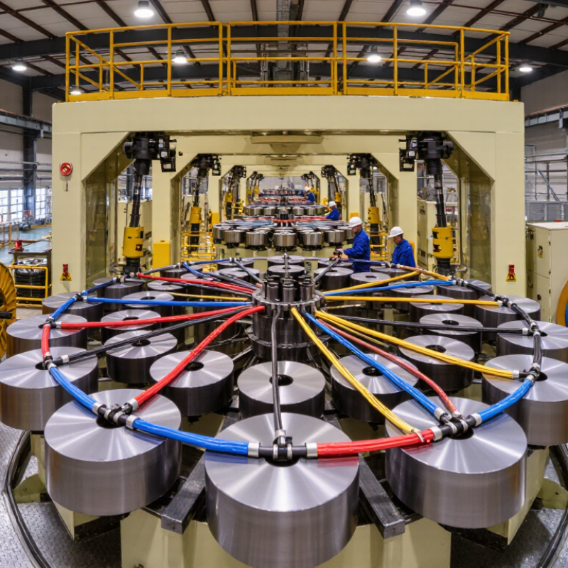
A bow-type laying-up machine brings several insulated conductors together and twists them into a cable core. Its rotating bow carries the conductors around a central axis, creating a controlled lay. Depending on the production design, the machine may also handle fillers or a central support element. The result is a more compact assembly that can proceed to sheathing or another downstream process.
During operation, payoff units feed conductors toward the closing point while tension controls help keep them aligned. The bow’s speed and the line’s haul-off speed work together to set the lay length. A small mismatch can change the twist or place uneven stress on the insulation. That matters. Operators typically check conductor tension, bow balance, and the finished core’s diameter rather than relying on speed settings alone.
The machine’s role is not simply to make conductors turn. It must maintain a repeatable geometry without scuffing insulation or trapping gaps between cores. For example, a soft insulated conductor may need gentler tension than a stiffer one. Setup depends on cable construction, materials, and target dimensions, so one recipe rarely fits every job. Even a well-adjusted machine cannot correct poor incoming conductor quality, and that point is easy to overlook.
A bow-type laying-up machine brings several insulated wires together and twists them around a central core. Its rotating bow carries the wires through a circular path, creating a controlled helical lay. The bow’s speed and the line’s travel speed must stay coordinated. Small changes matter. If the lay is uneven, the finished cable may look lumpy or feel stiff during bending.
Pay-off units hold the supply reels and feed each wire toward the bow. Their tension controls help prevent slack, stretching, or crossed strands. The capstan pulls the assembled cable through the machine at a steady rate, while the take-up winds it onto a reel. These parts work as a system, not as isolated stations. A useful check is to inspect wire tension and reel alignment during setup, rather than relying on speed settings alone. That shortcut can miss a problem.
Demand for dependable cable production is rising. The International Energy Agency’s 2023 report, Electricity Grids and Secure Energy Transitions, says annual grid investment needs to exceed USD 600 billion by 2030, up from about USD 300 billion today. That figure is not a machine-performance benchmark, but it shows why consistent cable construction matters. In practice, operators still balance output against lay quality; faster is not always better. A slightly slower run may produce a cleaner, more uniform reel.
A bow-type laying-up machine brings several insulated cores together around a central element. A rotating bow carries the cores around that center while a capstan pulls the assembled cable forward. The relationship between bow speed and line speed determines the lay length: the distance the cable advances during one complete turn. Faster bow rotation or slower haul-off generally produces a shorter lay. Small changes matter. Operators check the finished lay rather than relying only on panel settings, because slippage and material variation can affect the result.
Lay direction depends on which way the bow rotates, creating either an S-lay or a Z-lay. The specified direction should match the cable design and any later manufacturing steps. Tension needs equal attention. Payoff brakes or tensioning devices help prevent cores from sagging, crossing, or pulling unevenly around the center. Too much tension may stretch insulation or distort the cable; too little can leave loose, irregular lays. A practical setup includes checking core paths, measuring lay length, and inspecting a short trial run. The first adjustment is not always right. Core stiffness, reel behavior, and machine condition can shift the result, so measured checks remain essential.
What Is a Bow Type Laying Up Machine?
Key Operating Data: Core Count, Bow Speed, and Lay-Length Range
A bow-type laying-up machine gathers insulated cores and twists them into a cable assembly. A rotating bow carries the cores around a central line, while take-up tension and haul-off movement help set the lay. It suits production where a consistent, compact assembly matters. Small tension changes can still create uneven spacing.
Core count affects loading and machine configuration. More cores need suitable pay-off positions, guides, and tension control. The maximum count is not just a brochure figure. Bow speed describes the bow’s rotation rate, but higher speed does not automatically mean higher output. Not always. The line must stay synchronized with the haul-off. Operators should check vibration, core crossover, and surface marks. Lay length is the axial distance covered in one complete twist. Its available range depends on machine design, core size, material stiffness, and cable construction.
Tips: Compare core count, bow speed, and lay-length range as one operating set. Ask for rated values under a clearly stated setup, then confirm them with a sample run. Inspect the cable after take-up, not only at the bow. A trial may reveal details a data sheet misses.
A bow type laying up machine brings insulated cable cores together and twists them into a stable assembly. For 0.6/1 kV power cables, the core arrangement must remain consistent through the lay. Operators watch tension, lay length, and cable diameter as the assembly leaves the rotating bow. Small changes matter.
IEC 60502-1 covers power cables with extruded insulation rated 0.6/1 kV, expressed as Uo/U. The standard addresses cable construction and testing, not the laying-up machine itself. A machine can help maintain repeatable geometry, but it cannot certify a finished cable. That distinction is easy to miss.
In practice, uneven tension may shift cores or distort the cable profile, making later sheathing less uniform. Check samples at the start of a run, then compare core position and outer diameter during production. Record the settings, too. They may need adjustment when core sizes or materials change. Manufacturing is rarely perfectly predictable.
| Dimension | Description | Cable Application or Rating |
|---|---|---|
| Machine type | A bow type laying up machine uses rotating bow-shaped carriers to gather insulated cores around a central element and form a cable core. | Used in manufacturing multicore power cables; the machine configuration depends on the cable design and production requirements. |
| Laying-up operation | Insulated cores are laid together with a controlled direction and pitch. Fillers or binding materials may be incorporated when specified by the cable design. | Creates the assembled core before subsequent operations such as inner sheathing, armouring, or outer sheathing. |
| Typical cable applications | Multicore low-voltage power cables for fixed installations and power distribution. | Applications may include building, industrial, and utility installations, subject to the cable construction and applicable installation rules. |
| IEC 60502-1 scope | IEC 60502-1 specifies construction, dimensions, and test requirements for power cables with extruded insulation and accessories for rated voltages from 1 kV up to 3 kV. | The standard includes cables rated U0/U of 0.6/1 kV and 1.8/3 kV. |
| 0.6/1 kV rating | U0 is the rated power-frequency voltage between a conductor and earth; U is the rated power-frequency voltage between conductors. | For a 0.6/1 kV cable, U0 = 0.6 kV and U = 1 kV. IEC 60502-1 associates this rating with Um = 1.2 kV, the maximum system voltage. |
| Higher rating in the standard | IEC 60502-1 also covers the rated-voltage designation 1.8/3 kV. | For this designation, U0 = 1.8 kV, U = 3 kV, and the associated maximum system voltage Um is 3.6 kV. |
| Conductor and insulation | Conductor material, conductor class, insulation compound, and core arrangement are specified by the cable design and relevant standards. | IEC 60502-1 covers cable construction and testing; conductor requirements are also addressed by applicable conductor standards, such as IEC 60228. |
| Important distinction | A bow type laying up machine is a production machine; it does not determine or certify the electrical rating of the finished cable. | The cable’s declared voltage rating and compliance must be established through its design, materials, and required tests against the applicable standard. |
Voltage designations are shown as U0/U. Always check the current edition of the applicable standard and the cable manufacturer’s technical documentation for a specific product.
„Thanks to the LUVIR technology, the solder resist process could be switched directly from the previously used mask exposure to direct exposure. As an outstanding digital solution on the market, this technology has been able to demonstrate fast process times and superior quality on our certified conventional ink in production. This allowed us to fully digitize the solder mask process at low cost – without process or ink adjustments. An excellent benefit to our production in Rot am See.“
Ralf Göhringer (Head of Production WE Rot am See)
I would definitely recommend the Limata machine and team for a future company purchase
Michael Greenaway
Compunetics Inc.
“The Limata ldi has been amazing!! Best thing we did was buy this machine”
Richard Brady
GM
Circuitlabs
“Since 2019, we have been running the Limata X1000 LDI system (including LUVIR for solder mask imaging) in daily production as an addition to our current process with film. The machine was capable of properly exposing Taiyo PSR-4000 BN (DI) solder mask types on normal to high-copper boards using a new and unique direct imaging process. The machine operating interface is very user friendly which allowed for a quick technical training curve. The pre-registration processing reduced several seconds of production time at every print. Limata support and service staff is incomparable. They supported our team every step of the way at basically any time of the day or night, with literally, an immediate response time, customizing the software interface to best fit our Operations and needs.
We have exposed more than 8,000 prints since end of October, on various solder mask colors and some resist film panels. Limata, has proven to be very capable and innovative. They are a strong contender in the industry.
We have very much enjoyed this project, and working with the team!
Thank you Limata for the continued support and being a part of our growth.”
Bill Sezate
Vice President, GM
Summit Interconnect
As a replacement to our current contact exposure process with film, the LIMATA X2000 system including LUVIR-Technology was capable of properly exposing non-LDI solder mask types using a direct imaging process. The machine offers cutting edge software with a very intuitive operating interface which allowed for quick technician training curve. The dual drawer system combined with pre-registration processing reduced several seconds of production time at every machine cycle. Limata support and service staff is world class. They added software patches to keep production running at shortest possible response times, customized the software interface to best fit our in-house Operations system, and even wrote a step-by-step machine processing manual. As a result of the project, we have exposed more than 16,000 times on various product types and solder mask brands/colors. Limata, in a very short timeframe as a company, has definitely shown they are truly innovative and will be challenging the industry of direct imaging for the top spot.
Kevin Beattie
Process Engineer
TTM Technologies
Forest Grove Division
