China’s Machined Motor Shaft industry has grown from basic turning workshops into a highly capable manufacturing network. Today, suppliers serve electric motors, industrial pumps, robotics, compressors, and automotive systems. Their strengths include CNC turning, centerless grinding, heat treatment, keyway cutting, and high-volume inspection.
Dr. David A. Dornfeld, a respected manufacturing engineer, offered a principle that fits this market well: “Quality is built into the process, not inspected into the product.” That idea matters when a shaft must maintain tight runout, accurate journals, and stable hardness across thousands of pieces. A reliable manufacturer should explain material grades, machining tolerances, balancing methods, surface finishing, and inspection equipment. Vague promises are not enough.
The best China Machined Motor Shaft manufacturers usually show practical evidence. They provide drawings, sample reports, material certificates, and clear production timelines. They also understand that a shaft is not merely a round steel component. A small error near the bearing seat can create vibration, noise, heat, or premature failure. That detail is easy to overlook.
Still, no supplier is perfect. Some factories display impressive machines but lack consistent process control. Others communicate well but struggle with difficult geometries. Buyers should compare production records, not only website photographs. This guide examines leading manufacturers through capability, engineering experience, quality systems, customization, and customer support. It also recognizes an uncomfortable truth: the lowest quotation may become the most expensive choice after rework and downtime.
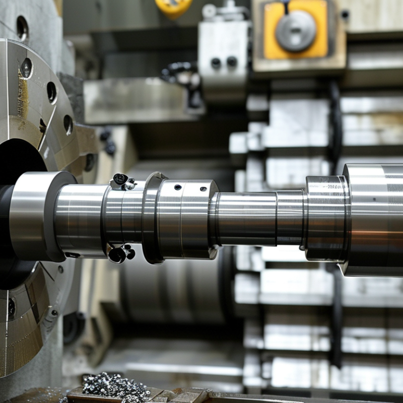
A machined motor shaft is the precision rotating part that transfers torque from a motor’s rotor to connected equipment. It is commonly produced from alloy steel, stainless steel, or hardened steel. Turning creates the main diameter, while milling forms keyways, flats, or splines. Grinding then improves bearing seats and surface accuracy.
Small errors matter. A shaft may look flawless and still create vibration. Uneven runout can damage bearings, seals, and couplings during continuous operation. ISO 21940 balancing guidance helps engineers control rotor imbalance, while ISO 286 defines tolerance systems for fits between shafts and bearings. In practice, manufacturers inspect diameter, concentricity, hardness, surface roughness, and magnetic cracks. A micrometer check alone is not enough.
The International Energy Agency has reported that electric motor systems consume about 46% of global electricity. This figure explains why shaft reliability affects large industrial energy costs. A poorly fitted shaft increases friction, noise, and maintenance demand. It may also reduce the motor’s useful life.
Material choice needs real operating data. A shaft carrying shock loads requires different treatment than one running quietly inside a small fan. Engineers should review torque, speed, temperature, load cycles, and corrosion exposure. I have seen specifications focus heavily on diameter while ignoring fillet radius. That is a mistake. Stress often gathers there. Supplier inspection reports, hardness records, and balancing results provide stronger evidence than appearance alone.
China Top Machined Motor Shaft Manufacturers?
How Machined Motor Shafts Are Designed and Manufactured
A machined motor shaft begins with operating conditions, not a standard diameter. Engineers review torque, speed, load direction, bearing seats, and available installation space. They also check whether the shaft needs a keyway, thread, spline, or balancing feature. Small errors here can create vibration, noise, or early bearing wear.
Manufacturing usually starts with alloy steel, stainless steel, or another specified material. The bar is cut slightly longer than the finished shaft. CNC turning forms the main diameter, shoulders, grooves, and chamfers. Milling creates keyways and flats with controlled depth. Heat treatment may improve strength, but it can also cause distortion. That risk should be measured, not assumed away.
After treatment, precision grinding brings bearing journals within tight tolerance. Technicians inspect diameter, roundness, surface roughness, and concentricity. A coordinate measuring machine can verify critical distances. Dynamic balancing is useful for high-speed motor applications. Traceable inspection records support consistent production across batches. In real workshops, drawings are not always perfect. A missing fillet radius or unclear tolerance can force interpretation. Experienced manufacturers ask questions before cutting metal. That extra discussion may feel slow, yet it prevents expensive rework. Final checks should include visual inspection, dimensional reports, material certificates, and protective packaging for transport.
When evaluating Chinese motor shaft manufacturers, begin with process evidence, not catalog photos. The IEA’s Energy Efficiency 2023 report estimates that electric motor systems consume nearly half of global electricity. Shaft accuracy therefore affects energy use, vibration, and service life.
Request material certificates, heat-treatment records, and batch traceability. Check whether the factory follows ISO 9001 controls and applies ISO 1101 for geometric tolerances. For rotating parts, ISO 21940 balancing procedures are highly relevant. Ask for measured runout, concentricity, hardness, and surface roughness. A useful report should show actual readings, not only pass marks. Tiny defects matter.
The U.S. Department of Energy’s Motor Systems Market Assessment reports that motor systems consume about 68% of industrial electricity in the United States. This supports stricter inspection of friction surfaces and dynamic balance. Review the manufacturer’s CNC capability, grinding accuracy, inspection equipment, and calibration records. Verify whether gauges are traceable to recognized standards. For automotive projects, controlled production planning and submission records may also be necessary.
Visit the plant when possible. Observe how operators protect finished journals from impact and corrosion. Ask for a sample shaft before approving mass production. One weakness remains easy to miss: a clean audit file cannot prove stable production. Compare several batches, and question results that look unrealistically perfect.
Leading China-based machined motor shaft manufacturers support motors used in pumps, fans, automation equipment, and electric vehicles. Experienced factories usually handle turning, milling, grinding, keyway cutting, and heat treatment under one production plan. They work with carbon steel, stainless steel, alloy steel, and other specified materials. A reliable manufacturer should provide material certificates, dimensional reports, and clear process records. Ask for samples before approving larger quantities. Real parts reveal more than polished brochures.
Tips: Check shaft diameter tolerance, concentricity, surface roughness, hardness, and balancing requirements. Request inspection data for critical areas, especially bearing seats and threaded ends. Confirm packaging details, because exposed metal can corrode during long transport.
A capable supplier will discuss drawings carefully instead of guessing. It should explain how cutting tools, grinding allowance, and heat treatment may affect final dimensions. Look for calibrated measuring equipment, skilled inspectors, and traceable batch numbers. Production photos can help, but independent sample inspection is stronger evidence. Some suppliers promise every tolerance too easily. That deserves attention. Manufacturing quality can vary between batches, even with documented procedures. A dependable factory admits process limits and suggests practical revisions when a design is difficult to produce. Clear communication about minimum order quantities, lead times, replacement procedures, and export documents also reduces purchasing risk. Small details matter.
China Top Machined Motor Shaft Manufacturers: How to Select the Right Manufacturer for Your Application
Selecting a top machined motor shaft manufacturer requires more than comparing prices. Shaft accuracy affects vibration, noise, bearing life, and energy loss. The International Energy Agency reports that electric motor systems consume about 45% of global electricity. Small design errors can therefore create long-term operating costs. Ask manufacturers for material certificates, heat-treatment records, and dimensional inspection reports.
Tips: Send a complete drawing, tolerance table, load data, speed range, and surface-finish requirements. Request a first-article sample before approving mass production. Confirm whether inspections use calibrated CMM equipment. ISO 9001 certification is useful, but it does not replace process evidence. Ask for corrective-action records when defects occur.
Application fit matters more than factory size. For high-speed motors, check concentricity, dynamic balancing, and journal roundness. For heavy-duty equipment, examine fatigue calculations, keyway strength, and corrosion protection. The U.S. Department of Energy identifies motor-driven systems as a major share of industrial electricity use, so reliable shaft alignment deserves serious attention. A cheaper shaft may increase downtime through hidden runout or poor hardness control. That is easy to underestimate.
Review production capacity, traceability, packaging, and export experience. Verify lead times with recent records, not promises. A supplier may offer excellent machining but weak technical communication. That gap can become expensive. Independent inspection before shipment adds cost, yet it can expose problems early. Reconsider the specification when necessary; an unnecessarily tight tolerance may raise price without improving performance.
| Selection Dimension | Typical Technical Reference | Application Consideration | What to Verify with the Manufacturer |
|---|---|---|---|
| Shaft Material | Common options include carbon steel, alloy steel, stainless steel, and hardened steel. Typical grades may include medium-carbon steel, chromium-molybdenum alloy steel, and corrosion-resistant stainless steel. | Select according to torque, bending load, wear, corrosion exposure, operating temperature, and required heat treatment. | Material certificate Chemical composition Heat-treatment record Confirm that the material grade and condition match the approved drawing. |
| Diameter and Overall Length | Custom motor shafts are commonly produced from small precision shafts below 10 mm in diameter to larger industrial shafts above 50 mm. Overall length depends on the motor frame and assembly design. | Diameter affects torsional strength and stiffness; length affects deflection, critical speed, and bearing arrangement. | Review the manufacturer’s machining range, chucking capability, bar capacity, and ability to control long-shaft concentricity. |
| Dimensional Tolerance | Non-critical dimensions may use general machining tolerances, while bearing seats, seal diameters, and coupling locations often require tighter tolerances defined by the engineering drawing. | Bearing and seal fits must be selected according to load, rotation speed, temperature, lubrication, and assembly method. | Ask for sample inspection data, calibrated measurement equipment, process capability information, and a clear interpretation of drawing tolerances. |
| Runout and Concentricity | Precision motor-shaft applications may require runout limits in the micrometre range at bearing seats or other functional surfaces. The exact value must be specified on the drawing. | Excessive runout can cause vibration, bearing wear, seal leakage, noise, and reduced motor efficiency. | Verify inspection methods such as V-block or centre measurement, datum control, probe resolution, and inspection temperature. |
| Surface Finish | Bearing seats and seal surfaces commonly require a smoother finish than non-functional turned surfaces. Surface roughness values should be stated as Ra on the engineering drawing. | Surface finish influences bearing seating, oil-film formation, seal performance, friction, and wear. | Confirm grinding, polishing, or superfinishing capability and request surface-roughness inspection records for critical areas. |
| Heat Treatment and Hardness | Induction hardening, carburizing, nitriding, or through-hardening may be used when higher wear resistance or fatigue strength is required. Hardness is normally specified in HRC, HV, or HB. | Use a hardened surface for wear-prone seats, splines, gears, or high-cycle applications, while retaining a tougher core where required. | Check hardness distribution, case depth where applicable, distortion control, post-treatment grinding, and hardness-test reports. |
| Keyways, Splines, Threads, and Features | Motor shafts may include parallel keyways, tapered sections, threaded ends, snap-ring grooves, flats, splines, and rotor mounting features. | Feature accuracy affects torque transmission, rotor positioning, coupling fit, assembly repeatability, and serviceability. | Confirm CNC turning, milling, broaching, spline machining, thread inspection, deburring, and feature-to-datum control. |
| Dynamic Balance | High-speed rotors and motor assemblies may require dynamic balancing to an applicable balance quality grade. The required grade depends on speed, rotor mass, and vibration limits. | Balancing is especially important for high-speed motors, long rotors, fans, pumps, and precision motion systems. | Request balancing speed, correction method, residual unbalance result, equipment calibration status, and the specified balance standard. |
| Inspection and Quality Documentation | A suitable quality package may include a dimensional inspection report, material certificate, hardness report, surface-finish result, coating record, and certificate of conformity. | Documentation requirements increase for safety-related, export-controlled, regulated, or high-volume applications. | Assess inspection equipment such as CMMs, roundness testers, hardness testers, roughness testers, and calibrated gauges. |
| Prototype and Production Capability | Prototype quantities may range from a few pieces to several dozen units, while production volumes can range from hundreds to many thousands of pieces per month. | The supplier should support both initial validation and stable production without changing critical processes unexpectedly. | Evaluate sample approval procedures, process validation, tooling ownership, production capacity, traceability, and change-control practices. |
| Lead Time and Supply Planning | Lead time depends on material availability, machining complexity, heat treatment, grinding, coating, balancing, inspection, and order quantity. | Multi-process shafts require more planning than simple turned shafts, particularly when external heat treatment or grinding is involved. | Request a process-based schedule, raw-material status, subcontractor controls, capacity plan, packaging method, and contingency plan. |
| Packaging and Corrosion Protection | Common controls include oil or vapor-phase corrosion protection, protective sleeves for precision seats, separators between parts, and moisture-resistant export packaging. | Packaging should prevent rust, impact damage, contamination, and deformation during storage and transportation. | Confirm packaging validation, shelf-life expectations, desiccant use, marking, lot identification, and protection of machined surfaces. |
| Total Cost of Ownership | The total cost includes material, machining, heat treatment, grinding, coating, inspection, packaging, tooling, logistics, rejects, and potential assembly problems. | The lowest unit price may not provide the lowest total cost if it creates vibration, premature bearing failure, rework, or unstable delivery. | Compare suppliers using a weighted score covering technical compliance, quality risk, delivery reliability, communication, tooling cost, and landed cost. |
„Thanks to the LUVIR technology, the solder resist process could be switched directly from the previously used mask exposure to direct exposure. As an outstanding digital solution on the market, this technology has been able to demonstrate fast process times and superior quality on our certified conventional ink in production. This allowed us to fully digitize the solder mask process at low cost – without process or ink adjustments. An excellent benefit to our production in Rot am See.“
Ralf Göhringer (Head of Production WE Rot am See)
I would definitely recommend the Limata machine and team for a future company purchase
Michael Greenaway
Compunetics Inc.
“The Limata ldi has been amazing!! Best thing we did was buy this machine”
Richard Brady
GM
Circuitlabs
“Since 2019, we have been running the Limata X1000 LDI system (including LUVIR for solder mask imaging) in daily production as an addition to our current process with film. The machine was capable of properly exposing Taiyo PSR-4000 BN (DI) solder mask types on normal to high-copper boards using a new and unique direct imaging process. The machine operating interface is very user friendly which allowed for a quick technical training curve. The pre-registration processing reduced several seconds of production time at every print. Limata support and service staff is incomparable. They supported our team every step of the way at basically any time of the day or night, with literally, an immediate response time, customizing the software interface to best fit our Operations and needs.
We have exposed more than 8,000 prints since end of October, on various solder mask colors and some resist film panels. Limata, has proven to be very capable and innovative. They are a strong contender in the industry.
We have very much enjoyed this project, and working with the team!
Thank you Limata for the continued support and being a part of our growth.”
Bill Sezate
Vice President, GM
Summit Interconnect
As a replacement to our current contact exposure process with film, the LIMATA X2000 system including LUVIR-Technology was capable of properly exposing non-LDI solder mask types using a direct imaging process. The machine offers cutting edge software with a very intuitive operating interface which allowed for quick technician training curve. The dual drawer system combined with pre-registration processing reduced several seconds of production time at every machine cycle. Limata support and service staff is world class. They added software patches to keep production running at shortest possible response times, customized the software interface to best fit our in-house Operations system, and even wrote a step-by-step machine processing manual. As a result of the project, we have exposed more than 16,000 times on various product types and solder mask brands/colors. Limata, in a very short timeframe as a company, has definitely shown they are truly innovative and will be challenging the industry of direct imaging for the top spot.
Kevin Beattie
Process Engineer
TTM Technologies
Forest Grove Division