Choosing a Centrifugal Flow Fan in 2026 is not just a matter of comparing airflow ratings. The right choice depends on the system it must serve. A fan moving air through a short, open duct faces different demands from one connected to filters, bends, and long ventilation runs. Small details matter. A clogged filter can raise resistance. A hotter airstream can change operating conditions. Even a quiet fan may become noisy when installed poorly.
This guide explains how to match fan performance to real operating requirements. It covers airflow, static pressure, fan curves, efficiency, sound levels, materials, and drive options. You will also learn which details to confirm in product data and installation manuals. Look beyond a headline capacity figure. Check that the published performance suits your system and its expected conditions. When available, compare test data from the manufacturer and ask a qualified supplier to review uncertain calculations. That check can prevent an expensive mismatch.
There is no universal best fan. A compact model may save space but leave little room for future changes. A larger unit may offer flexibility, yet consume more energy than necessary. I have seen specifications look convincing on paper and disappoint after installation; the duct layout was overlooked. That is worth remembering. The aim here is a practical, evidence-based selection—not a perfect answer for every building. Use the guide to ask sharper questions before you buy.
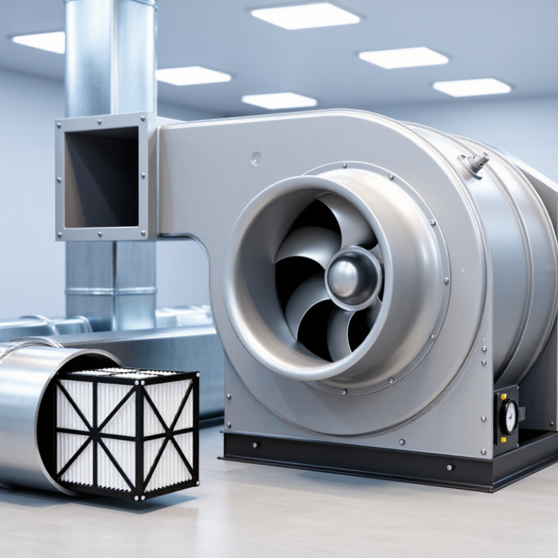
A centrifugal flow fan draws air through its inlet and spins it outward with a rotating impeller. The blades add speed to the air. Inside the curved housing, some of that speed becomes static pressure, which helps push air through ducts, filters, or equipment. Air moves outward. The process is straightforward, but fan performance depends on the whole system, not just the impeller.
Tips: Check the required airflow and pressure together. Measure duct length, bends, filters, and grilles where possible. Small losses add up. A fan that looks powerful on paper may deliver less air once connected to a restrictive system.
When choosing a fan in 2026, compare its performance curve with the system’s expected resistance. A common mistake is selecting by motor power or outlet size alone. Neither tells you exactly how much air will reach the room. Consider noise, available space, operating temperature, and maintenance access, too. On paper, a duct run can look tidy; real installations often have awkward bends or unexpected restrictions. Recheck assumptions before ordering, and ask for test data at the operating point you actually need.
Start with the air volume your process actually needs, in cubic metres per hour, and the pressure required to move it through the complete system. Include ducts, bends, filters, coils, dampers, and discharge points. A clean filter is not the only operating condition; account for the pressure rise as it collects dust. Specify whether the pressure value is static or total. They are not interchangeable.
The U.S. Department of Energy’s Improving Fan System Performance sourcebook recommends assessing the fan as part of its system, since system resistance shapes real operating performance.
Use measurements where possible, rather than sizing from a motor rating or an old fan’s nameplate. Record airflow and pressure at the expected operating points, including the least favourable condition. AMCA Publication 201, Fans and Systems, describes the fan laws: at constant air density, speed changes affect airflow roughly in proportion to speed, pressure to speed squared, and power to speed cubed.
A 10% speed increase therefore means about 10% more airflow, 21% more pressure, and 33% more power.
Small changes matter. These relationships are useful estimates, not a substitute for checking the manufacturer’s certified performance curve at your actual air density and duty point. That detail is easy to overlook.
A centrifugal fan’s wheel shape affects pressure, airflow, and particle handling. Forward-curved blades fit compact systems with modest pressure demands. Backward-inclined blades often offer better efficiency at higher pressures, especially with relatively clean air. Radial blades are sturdier around dust, but can be louder and use more power. Actual performance depends on the full system curve, not the wheel alone.
Material matters. Galvanized steel suits many dry indoor installations; aluminum can reduce weight, while stainless steel may help in damp or corrosive settings. Check the actual chemical exposure before choosing. For drives, direct drive is compact and avoids belt upkeep. Belt drive can offer flexibility in speed and motor placement, but belts need inspection and tension adjustment. The awkward part: a good fan can still perform poorly if ducts are restrictive.
Tips: Compare certified fan curves at your required airflow and pressure. Check temperature, dust, access, and noise limits. If using a speed controller, confirm motor compatibility. Leave room for maintenance; it is easy to overlook.
How to Choose a Centrifugal Flow Fan in 2026?
Evaluate Efficiency, Noise, and Operating Conditions
Choose a centrifugal flow fan based on the air it must move, not simply the largest motor available. Record the required airflow, static pressure, temperature, dust load, and operating hours. Compare fan curves at your expected duty point; peak efficiency alone can mislead. A fan near its best-efficiency region may use less power, but ducts, filters, and dampers affect real performance. Measure where you can.
Noise is not just a catalog decibel figure. Check how and where it was measured, including inlet and outlet conditions. A whistle near a grille may indicate turbulence or a poor transition, rather than a need for a larger silencer. During commissioning, listen for vibration and tonal noise near occupied spaces. A small speed reduction can help, though airflow may fall too. Small changes matter.
Tips: Test the fan with clean and loaded filters, and note airflow, power use, and sound. Check whether temperature, humidity, or corrosive particles call for different materials. Keep a simple operating log. It will not capture everything, but it can reveal changes that a tidy specification sheet misses.
| Fan Configuration | Typical Application | Airflow at Example Operating Point | Static Pressure | Approx. Fan Shaft Power | Approx. Fan Efficiency | Indicative Sound Pressure Level | Operating Conditions and Selection Notes |
|---|---|---|---|---|---|---|---|
| Forward-curved, low-pressure | Compact air-handling units and general ventilation | 0.45 m³/s (1,620 m³/h) | 250 Pa | 0.32 kW | 35% | Approximately 58 dB(A) at 1 m | Suitable for relatively low-resistance systems. Check motor loading carefully because this design can draw increasing power as airflow rises. |
| Backward-curved, medium-pressure | Commercial ventilation and air-handling systems | 1.20 m³/s (4,320 m³/h) | 500 Pa | 0.95 kW | 63% | Approximately 68 dB(A) at 1 m | A versatile option for moderate duct resistance. Its non-overloading power characteristic can help protect the motor when system conditions vary. |
| Airfoil-blade, high-efficiency | Large clean-air systems with steady operating demand | 4.00 m³/s (14,400 m³/h) | 700 Pa | 3.60 kW | 78% | Approximately 76 dB(A) at 1 m | Can deliver high efficiency near its selected duty point. Best suited to clean air; avoid applications where sticky deposits or heavy particulate buildup can affect the blades. |
| Radial-blade, robust construction | Dust collection and air streams containing coarse particles | 2.00 m³/s (7,200 m³/h) | 800 Pa | 2.50 kW | 64% | Approximately 79 dB(A) at 1 m | Often selected for durability in dirty or abrasive service. Confirm material, wear protection, conveying velocity, and particle characteristics for the specific process. |
| Backward-curved, high-pressure | Process exhaust and systems with higher duct resistance | 1.00 m³/s (3,600 m³/h) | 1,200 Pa | 1.80 kW | 67% | Approximately 74 dB(A) at 1 m | Provides higher pressure capability at a moderate airflow. Check the fan curve against the complete system resistance, including filters, coils, dampers, and duct fittings. |
Values are representative comparison examples, not certified product ratings. Approximate fan efficiency is calculated as airflow × static pressure ÷ fan shaft power. Sound levels are indicative A-weighted sound-pressure levels at 1 m and depend on installation, room acoustics, inlet and outlet conditions, and measurement method. For final selection, use the manufacturer’s certified fan curve and verify the required airflow, pressure, air density, temperature, altitude, motor power, control method, and acoustic limits at the actual operating point.
How to Choose a Centrifugal Flow Fan in 2026?
A fan’s catalogue rating is only a starting point. Check the required airflow and static pressure at the same duty point on its performance curve. Include duct losses, filter loading, and the air’s operating temperature; a clean-filter estimate can mislead. A spreadsheet can look precise while hiding a poor assumption. Small details matter. Ask for the curve, motor data, sound levels, and stated test conditions, then compare them with the project specification. Confirm that the materials and electrical protection suit the actual environment.
Compliance and upkeep deserve equal attention. Request applicable conformity documents and verify them against local codes and site requirements. Check what the documents cover, not just whether they exist. Consider access before purchase: can a technician reach the bearings, impeller, and inspection panels without dismantling nearby equipment? Ask about lubrication intervals, belt tension where relevant, cleaning, and replacement-part availability. Keep the maintenance plan realistic. During commissioning, record airflow, pressure, vibration, and motor current as a baseline. Recheck those readings after filters or operating conditions change. I would not assume every vibration has one cause; installation, imbalance, and wear can overlap. A clear service record makes the next diagnosis less guesswork.
„Thanks to the LUVIR technology, the solder resist process could be switched directly from the previously used mask exposure to direct exposure. As an outstanding digital solution on the market, this technology has been able to demonstrate fast process times and superior quality on our certified conventional ink in production. This allowed us to fully digitize the solder mask process at low cost – without process or ink adjustments. An excellent benefit to our production in Rot am See.“
Ralf Göhringer (Head of Production WE Rot am See)
I would definitely recommend the Limata machine and team for a future company purchase
Michael Greenaway
Compunetics Inc.
“The Limata ldi has been amazing!! Best thing we did was buy this machine”
Richard Brady
GM
Circuitlabs
“Since 2019, we have been running the Limata X1000 LDI system (including LUVIR for solder mask imaging) in daily production as an addition to our current process with film. The machine was capable of properly exposing Taiyo PSR-4000 BN (DI) solder mask types on normal to high-copper boards using a new and unique direct imaging process. The machine operating interface is very user friendly which allowed for a quick technical training curve. The pre-registration processing reduced several seconds of production time at every print. Limata support and service staff is incomparable. They supported our team every step of the way at basically any time of the day or night, with literally, an immediate response time, customizing the software interface to best fit our Operations and needs.
We have exposed more than 8,000 prints since end of October, on various solder mask colors and some resist film panels. Limata, has proven to be very capable and innovative. They are a strong contender in the industry.
We have very much enjoyed this project, and working with the team!
Thank you Limata for the continued support and being a part of our growth.”
Bill Sezate
Vice President, GM
Summit Interconnect
As a replacement to our current contact exposure process with film, the LIMATA X2000 system including LUVIR-Technology was capable of properly exposing non-LDI solder mask types using a direct imaging process. The machine offers cutting edge software with a very intuitive operating interface which allowed for quick technician training curve. The dual drawer system combined with pre-registration processing reduced several seconds of production time at every machine cycle. Limata support and service staff is world class. They added software patches to keep production running at shortest possible response times, customized the software interface to best fit our in-house Operations system, and even wrote a step-by-step machine processing manual. As a result of the project, we have exposed more than 16,000 times on various product types and solder mask brands/colors. Limata, in a very short timeframe as a company, has definitely shown they are truly innovative and will be challenging the industry of direct imaging for the top spot.
Kevin Beattie
Process Engineer
TTM Technologies
Forest Grove Division