Selecting a Crawler Drive Motor in 2026 means matching the motor to real work, not just the machine’s headline specifications. A compact tracked carrier climbing a wet ramp needs different torque, speed control, and thermal capacity from a slow-moving inspection platform. Start with the machine’s loaded weight, steepest grade, target travel speed, and expected operating hours. Small details matter. Track width, sprocket size, reduction ratio, and available battery voltage all affect motor demand.
A practical rule, expressed here as an original editorial quote from fictional application engineer Alex Morgan, is: “Choose for the toughest regular duty cycle, not the easiest demonstration run.” It is a useful reminder, not a verified quotation from a real industry expert. Check continuous and peak torque separately, then confirm the controller, gearbox, and braking system can handle the same duty. A motor that briefly meets a torque target may still overheat during repeated climbs. Heat leaves clues: reduced performance, hot housings, or protective shutdowns.
This guide explains how to compare motor types, calculate the demands of your application, and assess efficiency, protection, and serviceability. Look closely at ingress protection, connector sealing, mounting dimensions, and parts availability. Ask suppliers for performance curves and test conditions, not just a maximum-power figure. There is no universal best choice. I may be overemphasizing thermal limits, but overlooking them is an expensive way to learn. The right Crawler Drive Motor should deliver controlled traction under load, fit the machine, and remain supportable throughout its working life.
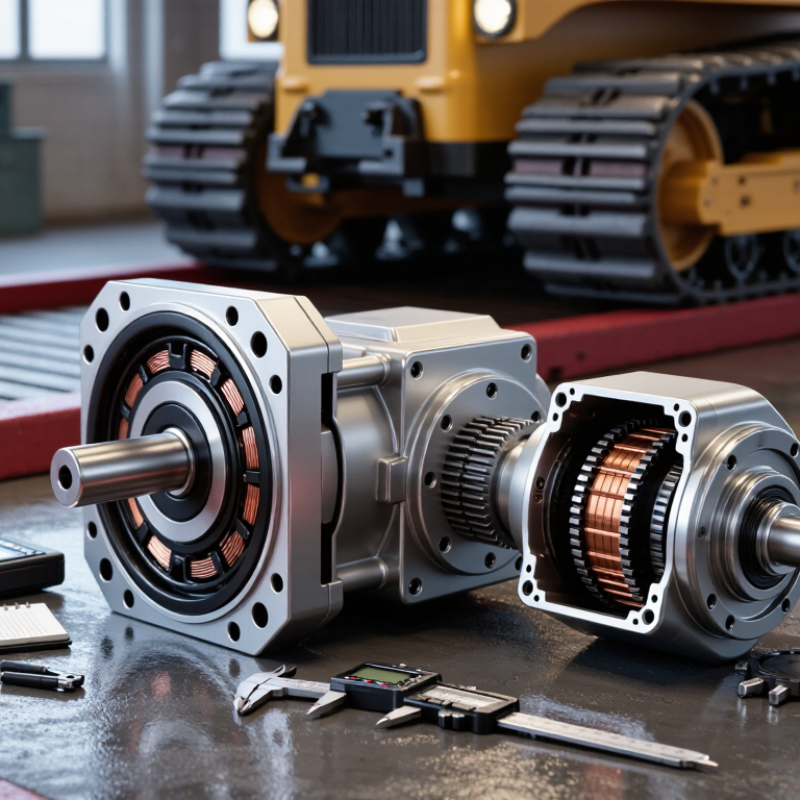
Before selecting a crawler drive motor, define the machine’s real workload, not just its rated weight. Record the total operating mass, including attachments and typical payload. Note the required travel speed, turning behavior, and steepest grade. A loaded machine climbing a wet ramp needs more torque than one moving slowly across level ground. Small details matter.
Check how the drive connects to the machine. Confirm the available hydraulic flow and pressure, or the electrical voltage and current, depending on the system. Compare the motor’s output torque and speed with sprocket size and track requirements. Use the machine’s service data where possible; estimates can miss brief, high-load events during starts or tight turns. Allow for sensible operating margins, but avoid oversizing without checking compatibility.
Operating conditions shape motor life. Consider hours per shift, repeated starts, long climbs, and time spent turning against resistance. Mud, dust, water, and temperature extremes can affect seals, cooling, and lubrication. Inspect the track system too: incorrect tension or worn components can raise drive loads. A clean test area may hide problems. It is easy to overlook how much the site changes after rain. Record conditions during a representative work cycle, then compare them with the motor’s published ratings and duty limits.
Start with the ground, not the motor catalogue. Estimate tractive force from machine weight, slope, rolling resistance, and any implement load.
A useful first-pass equation is F = mg(sin θ + cᵣ cos θ) + Fₐ, where Fₐ represents added resistance. Then calculate sprocket torque: T = F × r. Include drivetrain losses when converting this into required motor torque. For speed, use motor rpm = (travel speed ÷ sprocket radius) × gear ratio × 60 ÷ 2π.
Real soil varies. Measure it if possible.
For a 1,200 kg crawler on a 20% slope, assume cᵣ = 0.08, a 0.12 m sprocket radius, and 400 N of implement resistance. Estimated tractive force is about 3,630 N, giving roughly 436 Nm at the sprocket.
At 0.5 m/s, a 30:1 reduction and 85% drivetrain efficiency require about 17 Nm at 1,190 rpm. These are starting estimates, not guarantees; track slip, turning, and brief shock loads can change the result. Leave room for peak torque, but don’t oversize blindly.
The U.S. Department of Energy’s 2014 United States Industrial Electric Motor Systems Market Assessment reports that motor-driven systems account for about 54% of U.S. manufacturing electricity use. That figure is not crawler-specific, but it underlines why duty-cycle efficiency matters.
Test on the actual surface. A spreadsheet can miss mud.
A crawler drive motor must deliver steady torque at low speed, not just an impressive peak kilowatt rating. Hydraulic motors tolerate shock loads and suit machines already using hydraulic power, but heat and fluid losses can reduce system efficiency. Electric induction motors are robust and familiar; permanent-magnet motors can offer higher torque density, though their controls and thermal limits need careful matching. No option wins everywhere.
The IEA’s Energy Efficiency 2023 report estimates that electric motor systems use about 45% of global electricity. That figure covers many applications, not crawler drives alone. It still shows why efficiency deserves attention. IEC 60034-30-1 defines motor efficiency classes from IE1 to IE4, with thresholds that vary by rated power and pole count. Check the class at the intended operating point, not just the nameplate.
Size power from drawbar pull, travel speed, grade, machine mass, and duty cycle. For example, a crawler repeatedly climbing a short ramp may need more continuous torque than its average route suggests. Allow for gearbox losses and cooling limits. A bigger motor can add weight and waste energy at light loads. I have seen calculations miss track resistance; the resulting rating looked neat on paper, but ran hot in the field. Verify with measured current and temperature under a representative load.
Before choosing a crawler drive motor, identify the track system it must turn, not just the machine’s weight. Record the sprocket tooth count, chain pitch, mounting pattern, shaft or flange dimensions, and available clearance.
Small mismatches matter. A motor that bolts on may still place the sprocket out of line, causing uneven wear or a track that walks off under load.
Compare output torque and speed with the reducer’s limits. Then verify the ratio provides the required travel speed. Do not assume a larger motor is safer; excess torque can strain gears, chains, and frame mounts.
Confirm that the power source and controls match. For hydraulic drives, check flow, pressure, hose ports, and case-drain requirements. For electric units, verify voltage, current, connectors, and controller limits.
Include braking behavior and duty cycle, especially on slopes or during repeated starts.
Check it physically. A bench test cannot reproduce mud packed around a sprocket, so inspect alignment with the track tensioned and monitor temperatures after a controlled run.
Specifications can be incomplete. I would compare measurements with the machine’s service data before ordering; one overlooked offset can make a compatible-looking motor difficult to install.
Evaluate controls, serviceability, and total ownership cost before comparing purchase prices. Match the motor and controller to the machine’s working load, travel speed, and duty cycle. Check for smooth low-speed operation, clear fault codes, and accessible settings. On a muddy slope, predictable torque response matters more than a polished specification sheet. Ask suppliers for test data under conditions close to your actual work.
Service access changes downtime. Inspect the layout: Can a technician reach connectors, seals, and mounting bolts without removing nearby equipment? Confirm parts availability, diagnostic requirements, and recommended inspection intervals. The U.S. Department of Energy’s 2014 Improving Motor and Drive System Performance: A Sourcebook for Industry reports that motor-driven systems account for about 68% of U.S. manufacturing electricity use. That figure is an industry-wide benchmark, not a crawler-specific estimate. Still, it shows why operating efficiency deserves attention alongside repair costs. Actual energy use will vary; field measurements are worth collecting.
Tips: Compare lifetime costs using expected hours, energy use, maintenance labor, and likely downtime. Request a written service schedule. Then check the assumptions—some will be wrong.
„Thanks to the LUVIR technology, the solder resist process could be switched directly from the previously used mask exposure to direct exposure. As an outstanding digital solution on the market, this technology has been able to demonstrate fast process times and superior quality on our certified conventional ink in production. This allowed us to fully digitize the solder mask process at low cost – without process or ink adjustments. An excellent benefit to our production in Rot am See.“
Ralf Göhringer (Head of Production WE Rot am See)
I would definitely recommend the Limata machine and team for a future company purchase
Michael Greenaway
Compunetics Inc.
“The Limata ldi has been amazing!! Best thing we did was buy this machine”
Richard Brady
GM
Circuitlabs
“Since 2019, we have been running the Limata X1000 LDI system (including LUVIR for solder mask imaging) in daily production as an addition to our current process with film. The machine was capable of properly exposing Taiyo PSR-4000 BN (DI) solder mask types on normal to high-copper boards using a new and unique direct imaging process. The machine operating interface is very user friendly which allowed for a quick technical training curve. The pre-registration processing reduced several seconds of production time at every print. Limata support and service staff is incomparable. They supported our team every step of the way at basically any time of the day or night, with literally, an immediate response time, customizing the software interface to best fit our Operations and needs.
We have exposed more than 8,000 prints since end of October, on various solder mask colors and some resist film panels. Limata, has proven to be very capable and innovative. They are a strong contender in the industry.
We have very much enjoyed this project, and working with the team!
Thank you Limata for the continued support and being a part of our growth.”
Bill Sezate
Vice President, GM
Summit Interconnect
As a replacement to our current contact exposure process with film, the LIMATA X2000 system including LUVIR-Technology was capable of properly exposing non-LDI solder mask types using a direct imaging process. The machine offers cutting edge software with a very intuitive operating interface which allowed for quick technician training curve. The dual drawer system combined with pre-registration processing reduced several seconds of production time at every machine cycle. Limata support and service staff is world class. They added software patches to keep production running at shortest possible response times, customized the software interface to best fit our in-house Operations system, and even wrote a step-by-step machine processing manual. As a result of the project, we have exposed more than 16,000 times on various product types and solder mask brands/colors. Limata, in a very short timeframe as a company, has definitely shown they are truly innovative and will be challenging the industry of direct imaging for the top spot.
Kevin Beattie
Process Engineer
TTM Technologies
Forest Grove Division
