A Powerline Transformer is more than a box between a generator and a load. It sets voltage levels, supports reliable service, and influences a project’s cost for decades. Choosing one means matching electrical performance to real operating conditions. Think about peak demand, expected load growth, fault levels, installation space, and the utility connection. A unit that looks adequate on a specification sheet may run hot during repeated summer peaks. That detail matters.
Transformer engineering author John J. Winders, whose book Power Transformers: Principles and Applications is a technical reference, offers a useful design perspective. In paraphrase: “A transformer must be selected for the system it serves, not just its nameplate rating.” This is a guiding principle, not a verified verbatim quotation. For project teams, it means checking voltage ratio, impedance, insulation class, cooling method, and protection requirements together. Ask how the transformer will behave at partial load, during faults, and after years of exposure to dust, moisture, or temperature swings. Small details count. A few extra centimeters of clearance can simplify inspection; poor access can complicate routine maintenance. There is no perfect choice, and oversized equipment can bring avoidable expense and losses. Still, cutting capacity too closely may leave little room for growth. A sound selection balances efficiency, resilience, budget, and serviceability. The sections that follow examine these trade-offs and show what to verify before ordering a Powerline Transformer for your project.
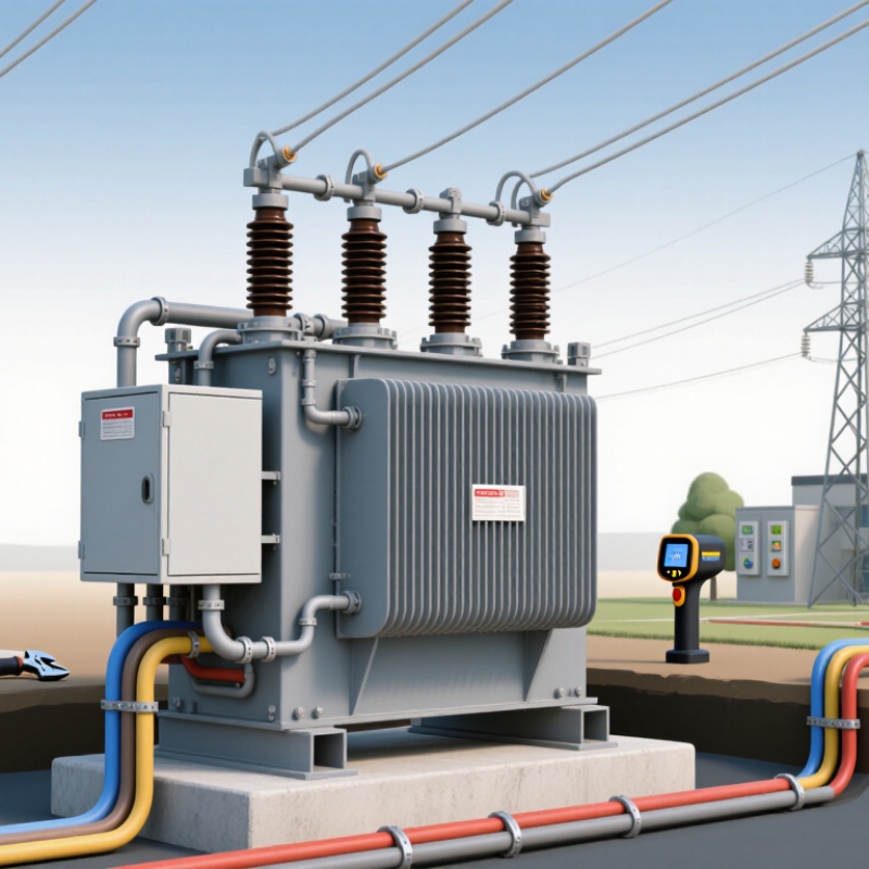
A powerline transformer transfers electrical energy between circuits through electromagnetic induction. Its windings surround a magnetic core, allowing voltage to change without a direct electrical connection between the circuits. It does not create energy. Some powerline transformers step voltage up for efficient transmission; others step it down for distribution to buildings and equipment. That distinction matters. The right type depends on where the transformer sits in the system and what the project needs.
A useful selection starts with the expected load, input and output voltages, phase, and frequency. Engineers also consider peak demand, impedance, cooling, insulation, and the installation environment. A unit beside a dusty industrial site may need different protection than one in a ventilated indoor room. Heat matters. So do clearances and maintenance access. A nameplate calculation is a good starting point, but real operating conditions can change the picture. Reviewing load data and site details with a qualified electrical professional helps expose those gaps before equipment is specified. The first estimate is rarely the whole story.
A powerline transformer changes voltage through electromagnetic induction. Electricity enters its primary winding, creating an alternating magnetic field in a laminated steel core. That field induces voltage in a separate secondary winding. The windings share a magnetic path, not a direct electrical connection. Their turns ratio determines whether voltage rises or falls.
On a distribution line, a transformer commonly reduces higher feeder voltage to the level used by nearby buildings. The current changes inversely: lower voltage means higher current for the same power. EIA estimates that transmission and distribution losses averaged about 5% of U.S. electricity supplied from 2018 through 2022. That matters. Transformer losses are one part of a larger system, not the whole story. The U.S. Department of Energy’s 2016 distribution-transformer standards analysis projected roughly 3.6 quadrillion Btu in cumulative energy savings over 30 years. Real sites are messier. Load swings, ambient heat, and installation details affect performance, so a nameplate rating alone cannot settle every project decision. Planning should match the transformer’s voltage, capacity, cooling method, and expected load profile to the actual site.
| Project Consideration | How It Works or Typical Characteristics | Why It Matters When Choosing |
|---|---|---|
| Voltage conversion | A distribution transformer uses electromagnetic induction to transfer AC power between primary and secondary windings. The turns ratio determines whether voltage is stepped down or, in some designs, stepped up. | Match the primary voltage to the available supply and the secondary voltage to the equipment or building load. Confirm system voltage and connection details with the utility or a qualified electrical engineer. |
| Typical distribution use | Utility distribution systems commonly use medium-voltage primary circuits and lower-voltage secondary circuits. Exact voltage levels vary by country, utility, and installation. | A suitable transformer can provide the voltage needed near the point of use, reducing the need to distribute utilization voltage over long distances. |
| Single-phase or three-phase | Single-phase units are commonly used for smaller loads and residential services; three-phase arrangements serve many commercial, industrial, and larger distribution loads. | Select a configuration that matches the supply system and load. Three-phase equipment generally requires a compatible three-phase source and connection arrangement. |
| Capacity and load | Transformer capacity is commonly stated in kilovolt-amperes (kVA). The required rating depends on the connected load, demand, power factor, starting currents, and expected growth. | Size the unit using an engineered load assessment rather than connected watts alone. Undersizing can cause overheating or voltage problems; excessive oversizing can increase initial cost and no-load losses. |
| Pole-mounted installation | A pole-mounted distribution transformer is installed on a utility pole and connected to overhead lines. It is typically used where overhead distribution is available and the utility approves the arrangement. | It can serve nearby loads without a ground-level transformer enclosure, but pole strength, clearances, access, weather exposure, and utility requirements must be considered. |
| Cooling and insulation | Distribution transformers may use liquid insulation and cooling or a dry-type design. Construction and permitted installation locations depend on the transformer design and applicable codes. | Consider fire protection, environmental conditions, maintenance access, spill controls where applicable, and local safety regulations when comparing designs. |
| Frequency and compatibility | Transformers are designed for a specified AC frequency, commonly 50 Hz or 60 Hz. Frequency, voltage, winding connections, and insulation ratings are shown on the nameplate. | Check the nameplate and technical documentation against the source and load. A voltage match alone does not establish that a transformer is suitable for the system. |
| Efficiency and operating losses | Transformers have no-load losses when energized and load losses that increase with current. Efficiency depends on design, rating, and operating load. | For long operating hours, compare certified loss data and applicable efficiency requirements. The most efficient option depends on the project's actual load profile and lifecycle costs. |
| Protection and safety | Protective devices and grounding arrangements are selected for the transformer, system, and installation. Their design can include overcurrent protection and measures for safe fault clearing. | Have protection, grounding, clearances, and installation work designed and reviewed by qualified professionals in accordance with local electrical codes and utility rules. |
| Best-fit project criteria | A powerline distribution transformer is a practical choice when the project needs a compatible voltage conversion point on an overhead distribution system. | Confirm supply availability, required capacity, phase, voltage, frequency, mounting method, environmental conditions, utility approval, and applicable standards before purchase or installation. |
Note: Typical applications and voltage arrangements vary by region and utility. Final selection and installation should be based on project-specific engineering and local requirements.
A powerline transformer can match the voltage and capacity needs of a distribution project. The key is defining the real load, not just copying a rating from an older installation. List the supply voltage, required output voltage, phase, frequency, and expected peak demand. Include motor starts or other short surges, since these can affect sizing. Numbers matter.
Site conditions matter too. A pole-mounted unit and a pad-mounted unit have different space, access, and installation needs. Check ambient temperatures, exposure to rain or salt air, available clearances, and how technicians will reach the equipment. A compact site may limit options. So can a narrow access road. These details are easy to overlook on a drawing, but costly to revisit after delivery.
The transformer should also suit the project’s operating pattern and maintenance plan. Ask about efficiency under typical loads, cooling method, impedance, protection, and compatibility with connected equipment. For sites with changing demand, allow room for realistic future growth without oversizing by guesswork. A common planning mistake is treating every project as a standard case. It isn’t. Confirm assumptions with qualified electrical professionals, and document any unresolved questions before selecting a unit.
Why Choose a Powerline Transformer for Your Project?
What Advantages Can It Offer?
A powerline transformer can provide dependable voltage conversion close to where electricity is used. By stepping voltage up or down, it helps match the supply to equipment needs and can limit avoidable distribution losses when properly selected. Its sturdy construction can suit outdoor installations and long service intervals. Small details matter. Performance still depends on load, cooling, insulation, and regular inspection.
For a workshop, farm, or utility extension, the right unit can simplify power distribution and accommodate future demand. Check rated capacity, input and output voltages, phase configuration, impedance, and site conditions. A unit that is too small may overheat during peak demand; an oversized one can increase purchase and operating costs. It is easy to rely on drawings alone, but field conditions vary. Confirm clearances, grounding, and access on site.
Tips: Compare measured peak demand with the transformer’s rating. Have a qualified electrical professional review protection and ventilation. Record unusual heat or noise. No transformer is maintenance-free.
A powerline transformer should match the electrical load, not just the project’s headline capacity. Start with the load. List every major device, its rated power, and how often it runs. A pump motor may draw much more current during startup than during steady operation. Include that brief surge when estimating the required kVA, and leave room for realistic future growth.
Next, confirm the primary and secondary voltages, phase, frequency, and connection requirements with the project’s electrical engineer or utility. Check the site conditions too. A transformer beside a dusty road, in a humid enclosure, or under direct sun may need different protection and cooling provisions. Review impedance and voltage regulation, since these affect fault current and the voltage delivered to equipment. The nameplate is useful, but it cannot describe every operating condition.
Compare candidate units against applicable installation requirements, available space, mounting method, and maintenance access. Ask for documented test data and verify that the selected unit suits the expected duty cycle. A neat spreadsheet can still miss an awkward detail, such as a motor starting while other loads are already running. I have seen planning estimates look convincing until that timing was checked. It is worth revisiting the assumptions before purchase. Then confirm the final specification with qualified electrical personnel and the utility, especially where connection details are still uncertain.
„Thanks to the LUVIR technology, the solder resist process could be switched directly from the previously used mask exposure to direct exposure. As an outstanding digital solution on the market, this technology has been able to demonstrate fast process times and superior quality on our certified conventional ink in production. This allowed us to fully digitize the solder mask process at low cost – without process or ink adjustments. An excellent benefit to our production in Rot am See.“
Ralf Göhringer (Head of Production WE Rot am See)
I would definitely recommend the Limata machine and team for a future company purchase
Michael Greenaway
Compunetics Inc.
“The Limata ldi has been amazing!! Best thing we did was buy this machine”
Richard Brady
GM
Circuitlabs
“Since 2019, we have been running the Limata X1000 LDI system (including LUVIR for solder mask imaging) in daily production as an addition to our current process with film. The machine was capable of properly exposing Taiyo PSR-4000 BN (DI) solder mask types on normal to high-copper boards using a new and unique direct imaging process. The machine operating interface is very user friendly which allowed for a quick technical training curve. The pre-registration processing reduced several seconds of production time at every print. Limata support and service staff is incomparable. They supported our team every step of the way at basically any time of the day or night, with literally, an immediate response time, customizing the software interface to best fit our Operations and needs.
We have exposed more than 8,000 prints since end of October, on various solder mask colors and some resist film panels. Limata, has proven to be very capable and innovative. They are a strong contender in the industry.
We have very much enjoyed this project, and working with the team!
Thank you Limata for the continued support and being a part of our growth.”
Bill Sezate
Vice President, GM
Summit Interconnect
As a replacement to our current contact exposure process with film, the LIMATA X2000 system including LUVIR-Technology was capable of properly exposing non-LDI solder mask types using a direct imaging process. The machine offers cutting edge software with a very intuitive operating interface which allowed for quick technician training curve. The dual drawer system combined with pre-registration processing reduced several seconds of production time at every machine cycle. Limata support and service staff is world class. They added software patches to keep production running at shortest possible response times, customized the software interface to best fit our in-house Operations system, and even wrote a step-by-step machine processing manual. As a result of the project, we have exposed more than 16,000 times on various product types and solder mask brands/colors. Limata, in a very short timeframe as a company, has definitely shown they are truly innovative and will be challenging the industry of direct imaging for the top spot.
Kevin Beattie
Process Engineer
TTM Technologies
Forest Grove Division