Choosing Telemecanique Sensors is not just a matter of matching a part number to a machine. The right choice depends on the target, sensing distance, operating speed, mounting space, and electrical interface. A sensor that works reliably beside a clean conveyor may fail near metal chips, vibration, or washdown spray. Small details matter.
The market context is clear. The International Federation of Robotics’ World Robotics 2024 report counted 4.28 million industrial robots in operation worldwide at the end of 2023. More automated equipment means more points where dependable detection matters. In an IFR statement on the industry’s growth, President Marina Bill said, “The global market value of industrial robot installations has reached an all-time high of 16.5 billion USD.” That figure describes the 2022 market, not sensor sales, but it shows the scale of automation shaping today’s design decisions.
This guide compares practical selection factors, including inductive, capacitive, photoelectric, and limit-switch technologies. It explains how target material, detection range, ambient light, temperature, ingress protection, and output type affect performance. Check the product documentation against the actual installation, then test the sensor with the real target and machine cycle. That is not enough on paper alone. A prototype can reveal a blind spot that a specification sheet cannot. Telemecanique Sensors offers a broad range, but no brand can remove the need to verify fit, wiring, and environmental conditions.
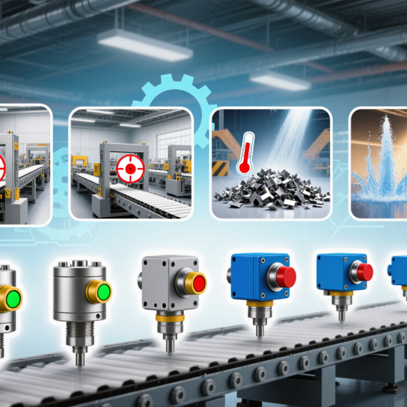
Before selecting a sensor, describe exactly what it must detect. Is the target metal, plastic, liquid, or a moving package? Note its size, surface finish, and position. A dark, glossy label may behave differently from a matte carton, even on the same line. Small details matter.
Measure the sensing distance at the target’s nearest and farthest positions. Allow for vibration and mounting tolerances. Record the fastest target speed, too; a sensor that detects a stationary object may miss one passing quickly. Check ambient light, dust, moisture, washdown, and temperature where the device will operate. A clean test bench can be misleading. Real production conditions rarely stay that tidy.
Then define what the control system needs: switching output, response time, and acceptable detection repeatability. Consider what happens when the target is absent or misaligned. Can a false trigger stop a conveyor, or is a missed detection more costly? In practice, teams sometimes specify range before checking the target material. That is an easy assumption to make, and worth revisiting. Test a sample target in its actual position, with nearby machinery running, before finalizing the sensing requirements. A few minutes of observation can reveal glare, gaps, or movement that drawings leave out.
| Requirement | What to Define | Practical Examples and Selection Notes |
|---|---|---|
| Target material and properties | Identify the object’s material, size, shape, color, surface finish, and whether it is solid or liquid. | Inductive sensing is suited to metal targets. Capacitive sensing can detect many nonmetallic materials, including some liquids and powders, but performance depends on the target and setup. Photoelectric sensing can detect varied materials, with results affected by color, reflectivity, and transparency. |
| Sensing function | Specify whether the task is presence detection, position confirmation, counting, level detection, or distance measurement. | A discrete proximity sensor can signal that an object is present. A photoelectric arrangement may detect objects crossing a path, while an analog distance sensor can provide a changing measurement for position or gap monitoring. |
| Operating distance and tolerance | Record the minimum and maximum distance, target movement, mounting variation, and required detection margin. | Compare the required distance with the sensor’s rated sensing distance and specified operating conditions. Inductive sensing distance varies with target material and dimensions; optical sensing distance depends on the sensing arrangement and target properties. |
| Response and operating speed | Define target speed, shortest event duration, switching frequency, and the response time needed by the control system. | For fast-moving parts or closely spaced objects, check the sensor’s response time and switching frequency against the machine cycle. Include input filtering or controller scan time when calculating the total detection delay. |
| Mounting and available space | Measure the installation space and define mounting orientation, sensing-face position, clearance, and nearby metal or other sensors. | Confirm the sensor’s dimensions and mounting instructions. Flush and non-flush inductive installations can have different clearance requirements; adjacent sensors or metal structures may affect performance. |
| Environment and protection | Document ambient temperature, moisture, dust, washdown, oil, chemicals, vibration, and exposure to sunlight or other light sources. | Select an enclosure rating and temperature range that meet the actual installation conditions. Check material compatibility and any relevant impact, vibration, or optical-interference limitations in the product specifications. |
| Electrical interface | Specify supply voltage, output type, switching logic, load current, wiring method, and controller input requirements. | Check compatibility between the sensor output (for example, PNP or NPN) and the control input. Confirm normally open or normally closed behavior, connector or cable requirements, and allowable load current. |
| Reliability and safety needs | Define the consequence of a missed or false detection, required diagnostic behavior, maintenance access, and any safety-related function. | For ordinary process detection, evaluate repeatability and expected service conditions. If the sensor is part of a safety function, use equipment specifically rated for that function and follow the applicable risk assessment and safety standards. |
Choosing a detection method starts with the target, not the sensor’s maximum range. An inductive sensor suits metal parts, such as a steel bracket passing a few millimeters away. Its range is usually short, and target size or metal type can change the switching distance. Allow a margin rather than designing right at the limit.
For plastic bottles, powders, or liquids, a capacitive sensor may detect materials that inductive models cannot. But a wet film on the sensor face can affect the reading. A photoelectric sensor works well when a beam can reach the target; dark, transparent, or highly reflective surfaces may need careful setup. Background color and nearby shiny guards matter. Small details matter.
Ultrasonic sensing can help with clear objects or targets whose color varies, since it measures reflected sound rather than light. Soft or angled surfaces may return a weak echo, though, and close targets can fall inside the sensor’s blind zone. In a conveyor application, test with the actual target at its real speed and position. Test the actual setup. Record the switching point, then repeat with dust, vibration, and normal spacing changes. A clean bench test is useful, but it can be misleading. The best choice is the method that detects the intended object reliably without reacting to nearby equipment.
A sensor that works reliably on a clean test bench may struggle beside a hot motor or under repeated washdown. Assess the actual installation point, not just the general area. Record temperature extremes, moisture, dust, oil mist, vibration, and exposure to cleaning chemicals. Small details matter. A connector facing upward may collect water, while a cable routed beside a moving arm can wear through over time.
Tips: Check the sensor’s datasheet for temperature, ingress-protection, and chemical-resistance limits. Compare those values with measured site conditions, allowing room for unexpected peaks. Confirm the target material and sensing distance with a sample, if possible.
Operating conditions matter too. Note how quickly the target moves, how often the machine cycles, and whether nearby metal could affect sensing. Leave enough mounting clearance for adjustment and maintenance. A common mistake is choosing by sensing range alone; it can overlook heat, vibration, or a target’s changing position. If conditions vary by shift or season, monitor them before final selection. Recheck the setup after installation, especially if readings are inconsistent. My first estimate may be wrong; real operating data should guide the final choice.
Start with the rated sensing range, but treat it as a ceiling, not a guaranteed operating distance. A metal target, tilted bracket, or warm enclosure can reduce the usable margin. Choose a range that allows for movement and repeatable detection, not just nominal reach. Small margins matter.
Match the output type and voltage to the controller input before ordering; a PNP/NPN mismatch can make a working sensor appear dead. Check switching frequency and load current when targets move quickly or outputs drive relays. For variable positions, an analog output may provide useful detail, but it also requires suitable input scaling. Confirm normally open or normally closed behavior against the machine’s fault response.
Installation often decides whether the specification works. Check mounting clearance, sensing-face orientation, cable exit, and nearby metal that could cause interference. In wet, dusty, or vibration-prone locations, verify the enclosure rating and connector strain relief. Secure the cable without sharp bends. Test several real targets at operating speed and temperature. If detection flickers, revisit alignment and range; the first setup may not be the right one.
Verify system compatibility before comparing sensing ranges or prices. Confirm the sensor’s supply voltage, output type, and switching logic match the controller input. A PNP output connected to an incompatible input may produce unreliable signals—or no signal at all. Check whether the application needs normally open or normally closed operation. Then compare the target material, sensing distance, response frequency, and mounting space against the technical datasheet. Leave a practical margin; a target moving at the edge of the rated range can make detection inconsistent. Small details matter.
Environmental ratings need equal attention. IEC 60529 defines IP enclosure ratings, while IEC 60947-5-2 covers proximity switches. Use these references to assess dust, water exposure, and device type, but verify the exact product rating and installation limits. Also consider vibration, temperature, cable routing, and electrical noise near drives. Deloitte’s 2024 Smart Manufacturing Survey reported that 92% of manufacturers viewed smart manufacturing as important to competitiveness over the next three years. That trend makes reliable sensing more consequential, but it does not replace application-specific checks. A rating that looks sufficient on paper may still disappoint in a washdown area.
Tips: Before installation, test the sensor with the actual target and controller. Record the measured switching distance, supply voltage, and output state. If the reading is borderline, reconsider the mounting position or sensing range; field conditions are rarely as tidy as a specification sheet.
„Thanks to the LUVIR technology, the solder resist process could be switched directly from the previously used mask exposure to direct exposure. As an outstanding digital solution on the market, this technology has been able to demonstrate fast process times and superior quality on our certified conventional ink in production. This allowed us to fully digitize the solder mask process at low cost – without process or ink adjustments. An excellent benefit to our production in Rot am See.“
Ralf Göhringer (Head of Production WE Rot am See)
I would definitely recommend the Limata machine and team for a future company purchase
Michael Greenaway
Compunetics Inc.
“The Limata ldi has been amazing!! Best thing we did was buy this machine”
Richard Brady
GM
Circuitlabs
“Since 2019, we have been running the Limata X1000 LDI system (including LUVIR for solder mask imaging) in daily production as an addition to our current process with film. The machine was capable of properly exposing Taiyo PSR-4000 BN (DI) solder mask types on normal to high-copper boards using a new and unique direct imaging process. The machine operating interface is very user friendly which allowed for a quick technical training curve. The pre-registration processing reduced several seconds of production time at every print. Limata support and service staff is incomparable. They supported our team every step of the way at basically any time of the day or night, with literally, an immediate response time, customizing the software interface to best fit our Operations and needs.
We have exposed more than 8,000 prints since end of October, on various solder mask colors and some resist film panels. Limata, has proven to be very capable and innovative. They are a strong contender in the industry.
We have very much enjoyed this project, and working with the team!
Thank you Limata for the continued support and being a part of our growth.”
Bill Sezate
Vice President, GM
Summit Interconnect
As a replacement to our current contact exposure process with film, the LIMATA X2000 system including LUVIR-Technology was capable of properly exposing non-LDI solder mask types using a direct imaging process. The machine offers cutting edge software with a very intuitive operating interface which allowed for quick technician training curve. The dual drawer system combined with pre-registration processing reduced several seconds of production time at every machine cycle. Limata support and service staff is world class. They added software patches to keep production running at shortest possible response times, customized the software interface to best fit our in-house Operations system, and even wrote a step-by-step machine processing manual. As a result of the project, we have exposed more than 16,000 times on various product types and solder mask brands/colors. Limata, in a very short timeframe as a company, has definitely shown they are truly innovative and will be challenging the industry of direct imaging for the top spot.
Kevin Beattie
Process Engineer
TTM Technologies
Forest Grove Division
