Choosing the right Die Casting Mold starts with the part, not the machine. Alloy, wall thickness, geometry, annual volume, and acceptable tolerances all shape the decision. A thin rib may fill poorly; a deep pocket can trap air or complicate ejection. Small details matter. So does the cooling layout, which affects cycle time and dimensional stability.
The market context is significant, but it should not dictate tooling choices. Fortune Business Insights’ Die Casting Market report estimated the global market at approximately US$80.4 billion in 2023 and projected continued growth. That scale reflects broad demand, especially across sectors such as automotive and industrial equipment. It does not mean every project needs the most complex mold. NADCA’s Product Specification Standards for Die Castings offer useful guidance on tolerances, alloys, and design considerations. A qualified toolmaker can apply those standards to the actual component and production process.
A practical selection weighs hot-chamber or cold-chamber production, die material, cavity count, expected shot life, maintenance access, and total cost per acceptable part. Ask how the supplier plans to manage vents, gates, cooling channels, and wear areas. Request evidence from comparable production runs, not only a polished CAD model. A CAD model can look convincing. It cannot prove stable output. One uncomfortable truth: early estimates may miss costly revisions. Review the design with the foundry before committing to tooling, and document the assumptions behind the quote.
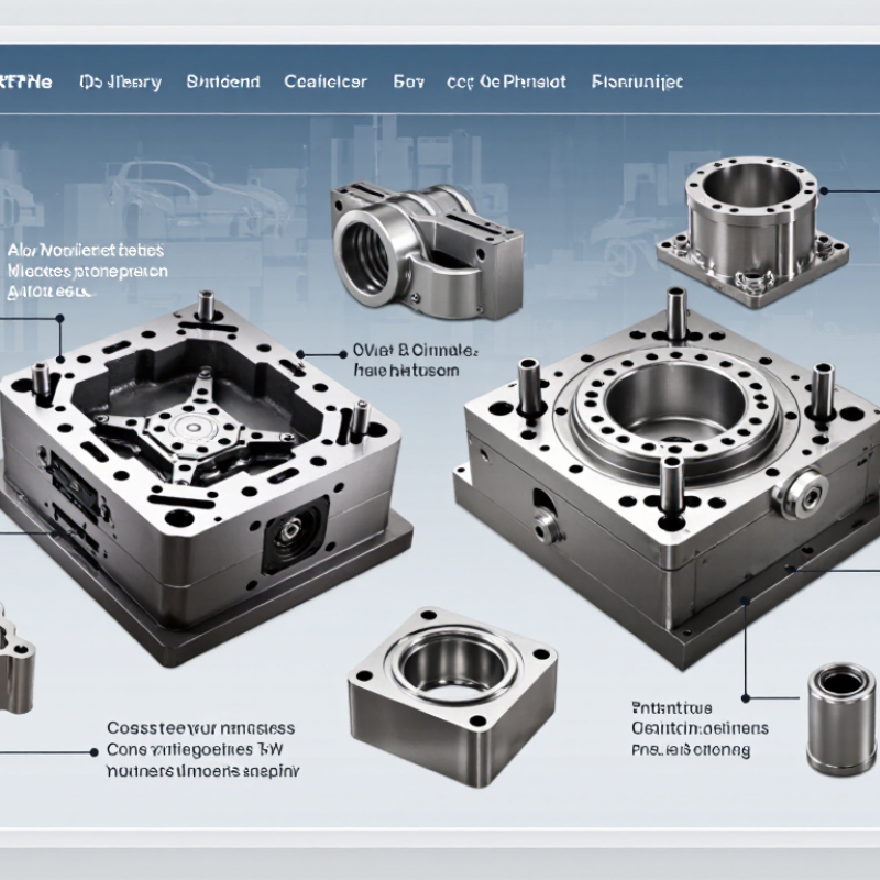
A suitable mold starts with a clear picture of the part. Record its alloy, dimensions, wall thickness, tolerance, and surface finish. Small details matter. A 2 mm wall may fill differently from a thicker section, so note thin ribs, deep pockets, and sharp corners. Identify any inserts or areas that need machining after casting. These details affect the mold layout, cooling channels, and ejection plan.
Production goals shape the decision, too. Estimate annual volume, target cycle time, and acceptable scrap levels. A high-volume program may justify a more durable, complex mold, while a short run may favor simpler tooling. Check that the casting machine can handle the mold’s size and locking force. Also consider maintenance access and expected tool life. A fast cycle is useful, but not if it causes uneven cooling or repeated defects. That assumption can fail. Early estimates are imperfect; confirm them with a casting specialist and, where practical, a trial run.
Tips: Share a 3D model, critical dimensions, and expected order volume. Mark surfaces that must remain visible. Ask how the mold will handle thin walls, venting, and likely wear points. A small review now can prevent costly redesigns later.
The right die casting mold starts with the casting process, not a steel grade. Hot-chamber machines suit alloys with relatively low melting temperatures, such as zinc. Cold-chamber casting is commonly used for aluminum alloys, which require a separate ladling step. That extra step affects cycle time and equipment layout. Details matter.
Next, match the mold material to the alloy, production volume, and part geometry. Hot-work tool steel is widely used because it tolerates repeated heating and cooling. Thin ribs and sharp corners can concentrate heat and stress, so they may need careful cooling and generous radii. A mold for a short run may not need the same wear resistance as one expected to produce hundreds of thousands of shots. That is not free.
Ask how the mold will be cooled, vented, maintained, and repaired. These practical choices can matter as much as initial hardness. For example, a thick section may cool slowly and increase cycle time, while a poorly placed cooling channel can leave uneven temperatures. Review trial-casting results, including fill, porosity, and surface finish, before locking in the design. There is rarely one perfect combination. A small change in alloy or part thickness can shift the best process and mold material. We sometimes underestimate that shift.
A die casting mold should be designed around the part’s geometry, alloy, and planned production volume. Check wall thickness, draft, parting lines, and ejector access before approving the tool. Small details matter: a sharp internal corner can restrict metal flow, while an awkward parting line may leave flash where sealing surfaces are needed. The North American Die Casting Association’s Product Specification Standards provide alloy-specific tolerance data; use the relevant tables when setting dimensions. Grand View Research estimated the global die casting market at USD 73.89 billion in 2023, underscoring the scale of production needs across the industry. Still, market growth alone cannot tell you which mold layout suits your part.
Cavity count affects output, tool cost, and process stability. A multi-cavity layout can raise throughput, but only if each cavity fills and cools consistently. Ask the toolmaker to review runner length, gate location, venting, and pressure balance in simulation. Compare those results with the real part geometry. Drawings can mislead.
Cooling deserves equal attention. Map likely hot spots around thick bosses, ribs, and gate areas, then place channels to remove heat evenly without weakening the mold. Poor cooling can increase cycle time and cause distortion; overly aggressive cooling may create temperature differences across the casting. NADCA guidance and production trials can help set realistic process limits, but simulation is not a guarantee. Leave room to adjust water flow and monitor temperatures during sampling. A slightly uneven result is useful evidence, not something to ignore.
The cheapest die casting mold is not always the least expensive choice. Compare its steel, heat treatment, machining accuracy, and inspection records. These details affect how well the mold resists heat, pressure, and repeated cycling. Ask how critical dimensions are measured and whether cooling channels and vents are checked before approval. Small defects matter.
Service life depends on more than the stated shot count. Alloy, part geometry, cycle temperature, and maintenance all influence wear. Request a realistic life estimate for your operating conditions, plus repair records for similar molds. Check areas around gates, slides, and the parting line; these often need attention first. Keep maintenance practical.
Compare total cost across the mold’s expected production life. Include the purchase price, planned maintenance, spare inserts, downtime, and scrap from inconsistent castings. A lower-cost tool may need frequent polishing or repairs, while a premium tool may not pay off at low volumes. Build a cost-per-good-part estimate using your forecast, then test it against a slower cycle or shorter tool life. Forecasts are imperfect. Leave room for uncertainty, and confirm which repairs can be completed locally without delaying production.
A die casting mold can look precise on a bench and still produce unstable parts. Test it on the intended machine, with the target alloy and documented process settings. Run consecutive shots long enough to reveal temperature drift, sticking, or inconsistent filling. Record cycle time, die temperature, injection pressure, and cooling behavior. Inspect samples for dimensions, flash, surface defects, and short fills. For internal porosity, use suitable non-destructive inspection or section selected parts. Some flaws hide.
Tips: Request a trial report with measurements from multiple cycles and every cavity. Check the parting line, vents, cooling channels, and ejector movement. A single clean casting is not proof of steady performance. Agree on acceptance limits before testing, so results are judged consistently.
Repeat the trial after any mold adjustment, then compare the new parts with the original measurements. Verify that the mold opens and ejects smoothly at the planned production pace. Note signs of uneven wear or coolant leaks, even if the samples pass. Testing has limits: a short run may not reflect every production shift. Record unresolved concerns rather than treating a passing sample as a guarantee.
„Thanks to the LUVIR technology, the solder resist process could be switched directly from the previously used mask exposure to direct exposure. As an outstanding digital solution on the market, this technology has been able to demonstrate fast process times and superior quality on our certified conventional ink in production. This allowed us to fully digitize the solder mask process at low cost – without process or ink adjustments. An excellent benefit to our production in Rot am See.“
Ralf Göhringer (Head of Production WE Rot am See)
I would definitely recommend the Limata machine and team for a future company purchase
Michael Greenaway
Compunetics Inc.
“The Limata ldi has been amazing!! Best thing we did was buy this machine”
Richard Brady
GM
Circuitlabs
“Since 2019, we have been running the Limata X1000 LDI system (including LUVIR for solder mask imaging) in daily production as an addition to our current process with film. The machine was capable of properly exposing Taiyo PSR-4000 BN (DI) solder mask types on normal to high-copper boards using a new and unique direct imaging process. The machine operating interface is very user friendly which allowed for a quick technical training curve. The pre-registration processing reduced several seconds of production time at every print. Limata support and service staff is incomparable. They supported our team every step of the way at basically any time of the day or night, with literally, an immediate response time, customizing the software interface to best fit our Operations and needs.
We have exposed more than 8,000 prints since end of October, on various solder mask colors and some resist film panels. Limata, has proven to be very capable and innovative. They are a strong contender in the industry.
We have very much enjoyed this project, and working with the team!
Thank you Limata for the continued support and being a part of our growth.”
Bill Sezate
Vice President, GM
Summit Interconnect
As a replacement to our current contact exposure process with film, the LIMATA X2000 system including LUVIR-Technology was capable of properly exposing non-LDI solder mask types using a direct imaging process. The machine offers cutting edge software with a very intuitive operating interface which allowed for quick technician training curve. The dual drawer system combined with pre-registration processing reduced several seconds of production time at every machine cycle. Limata support and service staff is world class. They added software patches to keep production running at shortest possible response times, customized the software interface to best fit our in-house Operations system, and even wrote a step-by-step machine processing manual. As a result of the project, we have exposed more than 16,000 times on various product types and solder mask brands/colors. Limata, in a very short timeframe as a company, has definitely shown they are truly innovative and will be challenging the industry of direct imaging for the top spot.
Kevin Beattie
Process Engineer
TTM Technologies
Forest Grove Division