Choosing the right Heat‑Proof Flexible Air Duct involves more than checking its maximum temperature rating. The duct must suit the air temperature, pressure, airflow, and installation environment. A product used near a furnace may face radiant heat, vibration, dust, and limited clearance. These details can change the correct selection.
A reliable evaluation begins with documented manufacturer data. Check the continuous operating temperature, short-term temperature limit, pressure range, wall construction, and fire-resistance classification. Compare those figures with real operating conditions, not optimistic estimates. Measure the connection diameter carefully. A loose fit can leak hot air, while excessive compression may restrict airflow.
Look closely at the inner liner, insulation layer, wire reinforcement, and outer jacket. Silicone-coated fiberglass may handle severe heat, while insulated fabric ducts can reduce heat loss in longer runs. Confirm that the material resists abrasion, moisture, oils, and cleaning chemicals when needed. Installation quality matters just as much. Support the duct properly, avoid sharp bends, and keep it away from direct flame.
Small details matter.
Experienced technicians often inspect the duct after several operating cycles. They look for discoloration, hardened coatings, sagging, loose clamps, and damaged reinforcement. These signs may reveal problems before failure occurs. A perfect choice does not exist. The best option balances safety, durability, airflow, service life, and budget. Even a highly rated duct can perform poorly when installed beyond its intended conditions. This guide explains how to compare specifications, question vague claims, and select a Heat‑Proof Flexible Air Duct with greater confidence.
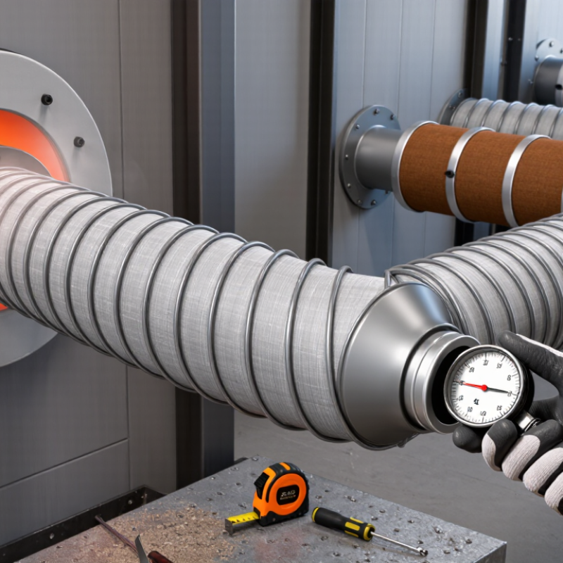
How to Choose the Right Heat Proof Flexible Air Duct?
Define the Required Temperature Range: 250°F, 500°F, or 1,000°F
Choosing a heat proof flexible air duct begins with measuring the real operating temperature. Do not rely only on the furnace setting. Use a calibrated thermometer near the duct connection, where heat is usually highest. Record both normal and peak temperatures during startup, shutdown, and continuous operation.
A 250°F duct may suit warm-air ventilation, drying equipment, or moderate exhaust. For ovens and high-temperature processing, a 500°F duct provides more protection. A 1,000°F duct is designed for severe heat, but its rating may apply only to intermittent exposure. Check the manufacturer’s data for continuous temperature, peak temperature, and exposure time.
Temperature is not the only concern. Hot air can expand the duct, weaken its coating, and damage nearby insulation. Select a duct with suitable inner layers, tight clamping hardware, and a bend radius that prevents crushing. Keep the duct away from sharp metal edges. Small installation mistakes matter.
Leave a margin.
In practice, I would avoid choosing a 250°F duct for an environment measured at 240°F. Heat spikes, sensor errors, and radiant heat can quickly remove that narrow margin. I once treated an average reading as reliable, then found the connection area was much hotter. That assumption needed correction. Inspect the duct after initial operation, especially around seams, clamps, and bends.
Define the required temperature range before selecting the duct construction and insulation system.
The chart compares three design-temperature reference points: 250°F (121°C), 500°F (260°C), and 1,000°F (538°C). Select a flexible air duct with a published continuous or intermittent temperature rating that meets or exceeds the actual air temperature, exposure time, airflow, pressure, and installation conditions. Always confirm the manufacturer’s technical data for the complete duct assembly, including the inner liner, reinforcement, insulation, and connectors.
Choosing a heat-proof flexible air duct starts with airflow, not appearance. A 500–800 fpm design velocity provides a practical sizing range for many ventilation systems. Calculate duct area with this formula: airflow in cfm ÷ velocity in fpm. For example, 1,200 cfm at 600 fpm requires about 2 square feet of internal area. That equals roughly a 19-inch round duct before installation losses.
ASHRAE Handbook—Fundamentals provides friction data based on airflow, duct size, and surface roughness. Its methods show why an undersized duct can create higher pressure loss and fan noise. SMACNA’s HVAC Duct Construction Standards also warn against sharp bends, sagging, and compressed flexible duct. These conditions reduce the effective area, even when the printed duct diameter looks correct. Flexible duct is rarely installed perfectly.
Heat resistance requires a separate check. Select a duct with a tested continuous temperature rating above the actual air temperature, not merely the expected room temperature. Verify insulation performance, vapor protection, pressure rating, and connection security. At 800 fpm, a long flexible run may become inefficient quickly. I would often choose a larger duct or shorter route after reviewing the field layout. The calculation is useful, but real installations can disagree.
| Nominal Duct Diameter (in.) | Approx. Internal Area (sq. ft.) | Airflow at 500 fpm (CFM) | Airflow at 600 fpm (CFM) | Airflow at 700 fpm (CFM) | Airflow at 800 fpm (CFM) | Suitable Design Airflow Range (CFM) | Typical Application |
|---|---|---|---|---|---|---|---|
| 4 | 0.087 | 44 | 52 | 61 | 70 | 44–70 | Small branch or spot-extraction connection |
| 6 | 0.196 | 98 | 118 | 137 | 157 | 98–157 | Small supply branch or compact ventilation run |
| 8 | 0.349 | 175 | 209 | 244 | 279 | 175–279 | Residential supply branch or moderate exhaust flow |
| 10 | 0.545 | 273 | 327 | 382 | 436 | 273–436 | Medium supply or return-air connection |
| 12 | 0.785 | 393 | 471 | 550 | 628 | 393–628 | Large residential or light-commercial air connection |
| 14 | 1.069 | 535 | 641 | 748 | 855 | 535–855 | High-volume supply or return-air run |
| 16 | 1.396 | 698 | 838 | 977 | 1,117 | 698–1,117 | Large air-handling or industrial ventilation connection |
| 18 | 1.767 | 884 | 1,060 | 1,237 | 1,414 | 884–1,414 | Very high-volume air distribution or exhaust |
| 20 | 2.182 | 1,091 | 1,309 | 1,527 | 1,745 | 1,091–1,745 | Large commercial or industrial air movement |
A heat proof flexible air duct must match the system’s temperature, pressure, and installation conditions. Fire performance deserves equal attention. Look for documentation showing compliance with UL 181, a key standard for air ducts and connectors. This evaluation can address flame resistance, air leakage, and structural behavior during testing. Do not rely only on the words “heat resistant.” They can describe temperature tolerance, not fire safety.
ASTM E84 Class 1 rating adds useful surface-burning information. Generally, Class 1 means a flame spread index of 25 or less and a smoke-developed index of 50 or less. These results help compare duct coverings and insulation materials. However, ASTM E84 does not replace UL 181 approval. The test methods measure different performance areas. A certificate may look reassuring, yet it might apply only to a specific construction, thickness, or installation method. That detail is easy to miss.
Tips: Ask for current test reports, product construction details, and temperature limits. Check whether the tested assembly matches your project. Inspect the duct after installation for crushed sections, sharp bends, and loose joints. These defects can reduce airflow and weaken expected performance. I have found that paperwork alone is not enough. On-site conditions often reveal the real risk. When evidence is incomplete, pause and verify it with a qualified engineer or code professional.
A heat-proof flexible air duct must match the system’s real pressure, not an optimistic estimate. Check both positive and negative pressure ratings on the technical data sheet. A duct may handle hot air well but collapse under suction. Leave a practical safety margin for startup surges, blocked filters, and long runs. These details are often missed.
Flexibility affects installation speed and airflow quality. A highly flexible duct can fit around beams and tight equipment spaces. However, excessive flexibility may create wrinkles, sagging, and unstable airflow. During installation, keep the inner liner smooth and support the duct at suitable intervals. It should bend without stretching the insulation or damaging the reinforcement wire. Small mistakes matter.
The minimum bend radius deserves careful attention. Measure the radius from the centerline of the duct, not from its outer edge. A bend tighter than the stated limit can flatten the passage and raise pressure loss. It may also create hot spots near the compressed section. For example, a duct requiring a 200 mm minimum radius should not be forced around a sharp 100 mm corner. That shortcut rarely saves time. It often causes rework.
Compare ratings under similar temperature conditions. Testing at room temperature may not represent high-temperature operation. Ask for documented performance data, material limits, and installation guidance. I have seen flexible ducts selected by diameter alone. That approach seems convenient, but it is incomplete. The safest choice balances pressure rating, usable flexibility, and the actual bend space available.
When choosing a heat proof flexible air duct, start with the actual operating environment. Do not trust peak temperature alone. Continuous heat can weaken adhesives, coatings, and reinforcement over time. Measure air temperature near the duct, not only at the heater outlet. A short spike and eight hours of steady heat require different materials. That distinction matters. Check the continuous temperature rating and test method.
Moisture, sunlight, and chemicals can change the selection. For damp spaces, choose construction with sealed coatings and corrosion-resistant reinforcement. Silicone-coated fiberglass often suits hot, humid air, but verify its moisture resistance. Outdoor installations need UV-stable outer layers. Otherwise, sunlight may cause cracking and brittleness. Chemical exposure requires a compatibility chart. Solvents, oils, acids, and cleaning vapors can attack different polymers quickly. PTFE-based materials may resist aggressive chemicals, while EPDM can perform well against selected weathering conditions. Never assume either material fits every chemical.
Installation details also affect service life. Keep the duct supported, smoothly routed, and away from sharp metal edges. Avoid tight bends near hot equipment. I have seen a properly rated duct fail because heat collected at a compressed section. That was an installation mistake, not a material failure. Ask for continuous-temperature data, UV testing, chemical compatibility information, and reinforcement details. If the application changes seasonally, review the choice again. Real conditions are often less predictable than the specification sheet.
„Thanks to the LUVIR technology, the solder resist process could be switched directly from the previously used mask exposure to direct exposure. As an outstanding digital solution on the market, this technology has been able to demonstrate fast process times and superior quality on our certified conventional ink in production. This allowed us to fully digitize the solder mask process at low cost – without process or ink adjustments. An excellent benefit to our production in Rot am See.“
Ralf Göhringer (Head of Production WE Rot am See)
I would definitely recommend the Limata machine and team for a future company purchase
Michael Greenaway
Compunetics Inc.
“The Limata ldi has been amazing!! Best thing we did was buy this machine”
Richard Brady
GM
Circuitlabs
“Since 2019, we have been running the Limata X1000 LDI system (including LUVIR for solder mask imaging) in daily production as an addition to our current process with film. The machine was capable of properly exposing Taiyo PSR-4000 BN (DI) solder mask types on normal to high-copper boards using a new and unique direct imaging process. The machine operating interface is very user friendly which allowed for a quick technical training curve. The pre-registration processing reduced several seconds of production time at every print. Limata support and service staff is incomparable. They supported our team every step of the way at basically any time of the day or night, with literally, an immediate response time, customizing the software interface to best fit our Operations and needs.
We have exposed more than 8,000 prints since end of October, on various solder mask colors and some resist film panels. Limata, has proven to be very capable and innovative. They are a strong contender in the industry.
We have very much enjoyed this project, and working with the team!
Thank you Limata for the continued support and being a part of our growth.”
Bill Sezate
Vice President, GM
Summit Interconnect
As a replacement to our current contact exposure process with film, the LIMATA X2000 system including LUVIR-Technology was capable of properly exposing non-LDI solder mask types using a direct imaging process. The machine offers cutting edge software with a very intuitive operating interface which allowed for quick technician training curve. The dual drawer system combined with pre-registration processing reduced several seconds of production time at every machine cycle. Limata support and service staff is world class. They added software patches to keep production running at shortest possible response times, customized the software interface to best fit our in-house Operations system, and even wrote a step-by-step machine processing manual. As a result of the project, we have exposed more than 16,000 times on various product types and solder mask brands/colors. Limata, in a very short timeframe as a company, has definitely shown they are truly innovative and will be challenging the industry of direct imaging for the top spot.
Kevin Beattie
Process Engineer
TTM Technologies
Forest Grove Division