Choosing the right Lfp Battery Bms starts with the battery itself, not a feature list. Confirm the cell chemistry, series count, capacity, and manufacturer’s charging limits. Lithium iron phosphate cells need protection settings suited to their voltage range; settings copied from another battery may be unsafe or reduce usable capacity. Check continuous current, peak current duration, and charging current against the pack’s datasheet and expected loads. A pump starting under load, for example, may briefly draw more current than it uses while running. Small mismatch, big problem.
Temperature monitoring also deserves attention. Check how many sensors are included, where they can be placed, and whether the BMS can stop charging or discharging outside specified temperature limits. Sensor placement matters: a probe left near a warm enclosure wall may not reflect cell temperature. Confirm the BMS supports the communication method your system actually uses, such as CAN, RS-485, or Bluetooth. Compatibility should be verified with the inverter or charger manufacturer, not assumed from a connector that looks familiar. Review the wiring diagram, balancing method, fault records, and technical support options before buying. A clear datasheet and responsive support are useful signs, though neither guarantees good performance. Be honest about what remains uncertain: product listings can omit details, and real installations reveal practical constraints. Measure the enclosure, check cable access, and leave room for service. The best choice is the one whose documented limits fit your cells and daily use.
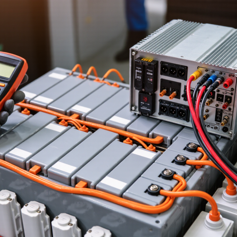
An LFP battery pack’s requirements start with its cell arrangement and intended use. Count the cells connected in series to establish the pack’s voltage range, then confirm the capacity and expected load. A small off-grid setup and a high-current machine need different protection settings. Check the cell manufacturer’s permitted charge and discharge limits, including temperature ranges. Do not guess. A BMS must monitor every series group, not just the pack’s total voltage.
Also consider the charger, load, and environment. Confirm that the BMS can interrupt charging and discharging at appropriate voltage and temperature limits. Its continuous and peak current ratings should match real operating conditions, with practical margin. Think about where the pack will sit: a sealed enclosure in a warm room can trap heat. Cell balancing matters too, especially when small voltage differences grow over repeated cycles. One easy detail to miss is sensor placement; a sensor far from the cells may not reflect their actual temperature.
Tips: Write down the pack voltage, capacity, maximum current, temperature range, and charger specifications before comparing BMS options. Check that the sensor leads reach the intended cell locations. If a requirement is uncertain, verify it against the cell documentation rather than relying on a convenient estimate. The first draft of a specification may need revision.
A BMS must match the pack’s full voltage range, not just its nominal voltage. For a common 16-cell series LFP pack, 3.2 V nominal per cell gives 51.2 V; at 3.65 V per cell, the charge limit is 58.4 V. Confirm these limits against the cell documentation, since cell specifications can differ. The BMS voltage rating must accommodate the pack’s maximum charge voltage and work with the charger’s settings. Close matters.
Size current ratings for both continuous demand and short bursts. A 2,000 W load on a 16-cell pack at 44.8 V draws about 45 A, before conversion losses. Check the BMS’s continuous rating at the expected temperature, then verify its peak-current limit and permitted duration against motor starts or inverter surges. Don’t rely on a headline amp rating alone. NREL’s 2024 Annual Technology Baseline uses four-hour duration as a utility-scale storage reference; that helps frame power versus stored energy, but does not set a BMS current rating. IEC 62619 addresses industrial lithium battery safety, not a universal pack rating. Real installations vary, and I would recheck the assumptions before choosing a margin.
An LFP battery BMS should show individual cell voltages, not just pack voltage. A pack reading can hide one weak cell behind a normal-looking average. Check temperature sensor coverage too: sensors should sit near cells and likely hot spots, not only beside the control board. The IEA’s Global EV Outlook 2024 reports that EV battery demand exceeded 750 GWh in 2023, up about 40% from 2022. That growth makes clear monitoring and fault records increasingly important.
Protection settings should address cell overvoltage, undervoltage, overcurrent, and temperature limits. Confirm that thresholds can be matched to the cell manufacturer’s specifications. For balancing, compare passive systems, which bleed excess energy as heat, with active systems, which transfer energy between cells. Active balancing may reduce wasted energy, but adds complexity. LFP voltage stays relatively flat across much of its charge range, so voltage alone can estimate state of charge poorly. A detail worth checking twice.
Tips: Ask for cell-level voltage logs and sensor locations. Test alarms and cutoff behavior with a qualified technician before relying on the pack. Also check whether the BMS reports balancing activity; a “balanced” status without supporting data is not very reassuring.
A suitable LFP battery management system should communicate clearly with the inverter, charger, and monitoring equipment in your setup. Check whether it supports CAN, RS-485, or UART, then confirm the required protocol, baud rate, pinout, and message mapping. Matching port names do not guarantee compatibility. A connector can fit while the data remains unreadable.
Ask for a communication specification and verify key readings, such as pack voltage, current, temperature, and alarm status. If possible, test the BMS with the intended equipment before installation. Watch for delayed updates or fault messages that fail to appear. Small details matter.
Operating conditions need the same attention. Compare the BMS limits with the battery’s expected charge and discharge current, temperature range, and installation environment. A system in a warm cabinet may need different thermal planning than one in a ventilated space. Consider dust, moisture, vibration, cable length, and electrical noise, too. I would not treat a published temperature range as a guarantee for every enclosure; airflow and sensor placement can change what the cells actually experience. It is easy to focus on the protocol and overlook these physical conditions. Check the specifications together, and leave margin where practical.
An LFP battery BMS must match the battery’s actual configuration, not just its chemistry. Check the number of cells connected in series and the pack’s operating-voltage range. A mismatch can cause inaccurate protection thresholds. Compare the BMS continuous and peak current ratings with the battery and connected equipment. Also confirm that its charge and discharge limits suit the cells’ specifications.
Look beyond a product label when checking safety certifications. Ask for current documentation, then confirm that the certified model matches the BMS you plan to install. Check whether the certification covers the component alone or the complete battery system; these are not always equivalent. Review protections for overvoltage, undervoltage, excess current, and temperature. Confirm sensor placement and any required communication settings. Small details matter. A sensor mounted far from the cells may not reflect their temperature well. Requirements can vary by application and location, so verify which standards apply to your installation.
Tips: Keep the battery datasheet, BMS manual, and certification documents together. Match model numbers and voltage limits line by line. A checklist can still miss an installation detail, so have a qualified technician review the setup before use.
„Thanks to the LUVIR technology, the solder resist process could be switched directly from the previously used mask exposure to direct exposure. As an outstanding digital solution on the market, this technology has been able to demonstrate fast process times and superior quality on our certified conventional ink in production. This allowed us to fully digitize the solder mask process at low cost – without process or ink adjustments. An excellent benefit to our production in Rot am See.“
Ralf Göhringer (Head of Production WE Rot am See)
I would definitely recommend the Limata machine and team for a future company purchase
Michael Greenaway
Compunetics Inc.
“The Limata ldi has been amazing!! Best thing we did was buy this machine”
Richard Brady
GM
Circuitlabs
“Since 2019, we have been running the Limata X1000 LDI system (including LUVIR for solder mask imaging) in daily production as an addition to our current process with film. The machine was capable of properly exposing Taiyo PSR-4000 BN (DI) solder mask types on normal to high-copper boards using a new and unique direct imaging process. The machine operating interface is very user friendly which allowed for a quick technical training curve. The pre-registration processing reduced several seconds of production time at every print. Limata support and service staff is incomparable. They supported our team every step of the way at basically any time of the day or night, with literally, an immediate response time, customizing the software interface to best fit our Operations and needs.
We have exposed more than 8,000 prints since end of October, on various solder mask colors and some resist film panels. Limata, has proven to be very capable and innovative. They are a strong contender in the industry.
We have very much enjoyed this project, and working with the team!
Thank you Limata for the continued support and being a part of our growth.”
Bill Sezate
Vice President, GM
Summit Interconnect
As a replacement to our current contact exposure process with film, the LIMATA X2000 system including LUVIR-Technology was capable of properly exposing non-LDI solder mask types using a direct imaging process. The machine offers cutting edge software with a very intuitive operating interface which allowed for quick technician training curve. The dual drawer system combined with pre-registration processing reduced several seconds of production time at every machine cycle. Limata support and service staff is world class. They added software patches to keep production running at shortest possible response times, customized the software interface to best fit our in-house Operations system, and even wrote a step-by-step machine processing manual. As a result of the project, we have exposed more than 16,000 times on various product types and solder mask brands/colors. Limata, in a very short timeframe as a company, has definitely shown they are truly innovative and will be challenging the industry of direct imaging for the top spot.
Kevin Beattie
Process Engineer
TTM Technologies
Forest Grove Division