Choosing the right MPO Patch cable starts with the link, not the label. Count the fibers, identify the connector type, and confirm whether your equipment requires a pinned or unpinned connector. Check polarity, too. A cable can fit neatly and still route signals incorrectly. That small detail matters.
As an illustrative line—not a verified quotation—from fictional MPO specialist Elena Park: “Match the cable to the transceivers and polarity plan before you match it to the rack.” It is a useful reminder, though real installations may need more checks. Confirm single-mode or multimode fiber, connector gender, insertion-loss limits, and required length. A short run across a server rack has different handling needs from a longer backbone link. Look closely at the product specification sheet; “MPO-compatible” alone does not settle every detail.
This guide explains how to compare those choices without guessing. You will learn how fiber count, polarity method, and connector configuration affect compatibility. We will also cover inspection and cleaning, since a speck of dust on an end face can disrupt a clean-looking connection. Measure the route, allow gentle bends, and leave enough slack for service. Not too much. Cable choice is partly technical and partly practical, and that balance is easy to overlook. Verify the specifications against your transceivers and equipment documentation before ordering.
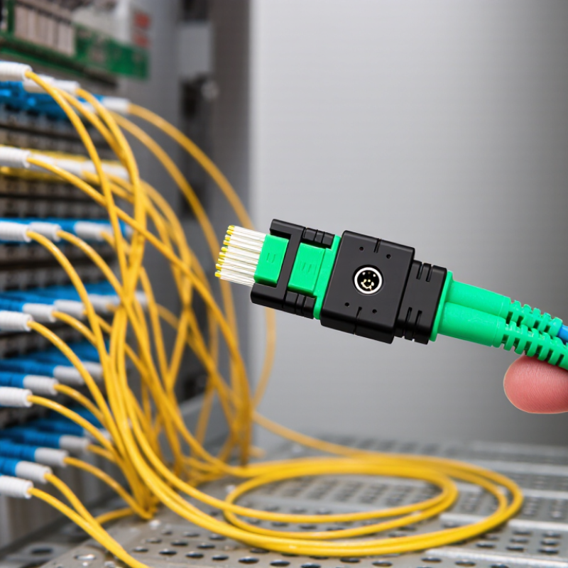
Before choosing an MPO patch cable, identify what the link connects, its speed, and its distance. A short switch-to-switch link may use multimode fiber, while longer building or campus runs often require single-mode OS2. Check the transceiver specifications too; the connector alone does not determine compatibility. Fiber type matters. Synergy Research Group’s 2024 data-center analysis projected global data-center capacity to more than double by 2030, reinforcing the need to plan cabling around actual growth and link requirements—not just today’s rack layout.
For multimode links, confirm the grade and supported reach. IEEE 802.3 specifications give 100GBASE-SR4 a maximum reach of 70 meters on OM3 and 100 meters on OM4. A few meters can change the right choice. For single-mode links, verify the optics’ wavelength and reach requirements before ordering OS2. Also check fiber count, polarity, and pin configuration against the equipment at both ends. These details are easy to overlook. A useful check is to compare the cable schedule with transceiver documentation and the labels on the installed equipment. It is tempting to assume matching MPO connectors mean matching fiber, but they do not. When documentation is incomplete, pause and verify rather than guessing.
Identify the application and match the cable’s fiber type to the supported link reach.
The chart shows representative maximum reaches for parallel-optics Ethernet applications. 40GBASE-SR4 and 100GBASE-SR4 use multimode fiber; 100GBASE-PSM4 uses single-mode fiber. Confirm the reach supported by the specific transceivers and link design before selecting a cable.
Cisco’s 2020 Annual Internet Report projected global IP traffic would reach 4.8 zettabytes annually by 2022. That growth makes accurate fiber planning important, but the report does not prescribe a cable count. Match the MPO fiber count to the transceiver and the full link design. Common options include 8, 12, 16, and 24 fibers.
Check the equipment specifications before ordering; unused fibers can complicate testing and troubleshooting. IEC 61754-7-1 defines MPO connector interfaces, while TIA-604-5 describes the FOCIS 5 interface.
Gender matters, too. A pinned MPO plug is male; an unpinned plug is female. Mating connectors generally need one of each. Keying controls how connectors align, but key-up and key-down descriptions can vary by component.
Confirm the required orientation at both ends, along with the polarity method used by trunks, cassettes, or transceivers. Small mismatches can leave a link dark, even when the connector appears seated. I still verify the port drawing, not just the cable label.
Tips: Before installation, inspect the end face, confirm fiber count and gender, then compare key orientation with the equipment documentation. Test polarity end to end. Never assume two MPO cables are interchangeable.
An MPO link may appear fully seated yet send light to the wrong receiving fibers. Treat polarity and pin configuration as separate checks. TIA-568.3-E describes three polarity methods: Method A keeps fiber positions straight, Method B reverses the array, and Method C flips adjacent fiber pairs. Select the method for the complete link, including trunk cables and cassettes, rather than relying on one patch-cord label. Labels can be wrong. A familiar configuration is not proof; it is easy to assume continuity without testing it.
Pinning matters just as much. A pinned MPO connector has guide pins; its mating connector must be unpinned and have guide-pin holes. Never force two pinned connectors together. IEEE 802.3-2022 specifies eight active fibers for 40GBASE-SR4 and 100GBASE-SR4, so fiber position directly affects transmit-and-receive alignment. Before installation, confirm the connector gender, key orientation, polarity method, and transceiver layout against the equipment documentation. Then verify the path with a polarity tester or suitable fiber test set. Test before deployment. A clean end face helps, but cleanliness cannot correct reversed polarity.
| Selection Check | Option | What It Means | How to Choose or Verify |
|---|---|---|---|
| Polarity | |||
| Polarity method | Type A — straight-through | For a 12-fiber MPO, fiber positions map 1→1, 2→2, continuing through 12→12. | Choose when the system design calls for a straight-through trunk. Check the polarity of the connected cassettes or equipment to confirm the complete link maps transmit to receive. |
| Polarity method | Type B — reversed | For a 12-fiber MPO, fiber positions map 1→12, 2→11, continuing through 12→1. | Choose when the link design requires a complete end-to-end position reversal. Confirm that the rest of the channel is designed for Type B polarity. |
| Polarity method | Type C — pairwise flipped | For a 12-fiber MPO, adjacent fiber pairs swap: 1↔2, 3↔4, continuing through 11↔12. | Choose only when the link design specifies pairwise polarity reversal. Verify compatibility across trunks, cassettes, and patch leads before installation. |
| Polarity check | End-to-end mapping | Polarity describes how fiber positions connect from one end of the link to the other; it is not determined by connector gender alone. | Use the system’s wiring plan or a polarity tester to confirm each required transmit path reaches the corresponding receive path. |
| Pin Configuration and Fiber Count | |||
| Connector gender | Pinned (male) | The MPO connector has guide pins that align the mating connector. | Use with an unpinned connector. Check the connector specification and inspect the end face; pins are not always easy to identify without magnification. |
| Connector gender | Unpinned (female) | The MPO connector has guide-pin holes but no guide pins. | Use with a pinned connector. Two connectors with pins should not be mated directly; confirm that the mating pair has complementary pin configurations. |
| Fiber count | 8-fiber | Provides eight fiber positions in the MPO array. | Match the cable fiber count to the transceiver, cassette, or equipment port. Confirm the required polarity and active positions for the application. |
| Fiber count | 12-fiber | Provides twelve fiber positions and is commonly used in MPO cabling systems. | Verify that the connected hardware supports a 12-fiber array and that its position mapping matches the selected Type A, Type B, or Type C design. |
| Fiber count | 24-fiber | Provides twenty-four fiber positions, typically arranged in a multi-row array. | Confirm the port and cable are both designed for 24 fibers. Check the applicable polarity map rather than applying a 12-fiber position map to the entire connector. |
| Final compatibility check | Connector, polarity, and fiber count | All three must match the intended channel design. | Before ordering, confirm MPO interface type, fiber count, pinned or unpinned end configuration, polarity method, and any required key orientation with the equipment documentation. |
Measure the complete route, not just the straight-line distance between panels. Include vertical runs, overhead trays, bends, and enough slack for service access. A cable that barely reaches can strain connectors when equipment shifts. Too much slack creates crowded trays and tight coils. Keep bends within the cable maker’s minimum radius, and avoid tying bundles so tightly that they flatten.
A useful field check is to trace the planned path with a tape measure before ordering. Add a modest service loop where technicians can reach it, but don’t add length everywhere by habit. That judgment can be imperfect: racks change, and drawings may miss obstacles. Recheck the route against the installed cabinets and tray layout.
Match the jacket to the actual environment. Indoor runs may need a rating suited to the building’s air-handling spaces; outdoor routes may require protection against sunlight, moisture, and temperature swings. Check the cable specification and local installation requirements rather than relying on color or appearance. A rugged jacket is not automatically the right choice for every space. Consider abrasion near tray edges and movement at cabinet entrances, too. The jacket protects the cable; it does not correct poor routing or protect exposed connectors.
An MPO cable can fit physically and still fail to carry the intended signals. Check the fiber type, core count, and connector gender against the equipment documentation. Confirm whether the ports require pinned or unpinned connectors, and note the key orientation. Small mismatches can leave a link dark or send traffic along the wrong fibers. Check polarity, too.
Optical performance needs measurement, not guesswork. Compare the cable’s specified insertion loss with the link budget, including losses from adapters and mated connections. Test each fiber with an appropriate optical loss test set at the wavelength used by the system. Inspect and clean both end faces before testing; dust can create unstable readings or damage a connector. Record results by fiber position. That detail helps locate a weak channel later.
Compatibility also depends on transceiver type, wavelength, and supported reach. A multimode cable is not a substitute for a single-mode link, even when both connectors appear identical. Verify the full path, including cassettes and trunk cables, because polarity can change at each transition. This step is easy to rush. I would recheck the port map before installation; documentation may be outdated, and one reversed pair can complicate troubleshooting.
„Thanks to the LUVIR technology, the solder resist process could be switched directly from the previously used mask exposure to direct exposure. As an outstanding digital solution on the market, this technology has been able to demonstrate fast process times and superior quality on our certified conventional ink in production. This allowed us to fully digitize the solder mask process at low cost – without process or ink adjustments. An excellent benefit to our production in Rot am See.“
Ralf Göhringer (Head of Production WE Rot am See)
I would definitely recommend the Limata machine and team for a future company purchase
Michael Greenaway
Compunetics Inc.
“The Limata ldi has been amazing!! Best thing we did was buy this machine”
Richard Brady
GM
Circuitlabs
“Since 2019, we have been running the Limata X1000 LDI system (including LUVIR for solder mask imaging) in daily production as an addition to our current process with film. The machine was capable of properly exposing Taiyo PSR-4000 BN (DI) solder mask types on normal to high-copper boards using a new and unique direct imaging process. The machine operating interface is very user friendly which allowed for a quick technical training curve. The pre-registration processing reduced several seconds of production time at every print. Limata support and service staff is incomparable. They supported our team every step of the way at basically any time of the day or night, with literally, an immediate response time, customizing the software interface to best fit our Operations and needs.
We have exposed more than 8,000 prints since end of October, on various solder mask colors and some resist film panels. Limata, has proven to be very capable and innovative. They are a strong contender in the industry.
We have very much enjoyed this project, and working with the team!
Thank you Limata for the continued support and being a part of our growth.”
Bill Sezate
Vice President, GM
Summit Interconnect
As a replacement to our current contact exposure process with film, the LIMATA X2000 system including LUVIR-Technology was capable of properly exposing non-LDI solder mask types using a direct imaging process. The machine offers cutting edge software with a very intuitive operating interface which allowed for quick technician training curve. The dual drawer system combined with pre-registration processing reduced several seconds of production time at every machine cycle. Limata support and service staff is world class. They added software patches to keep production running at shortest possible response times, customized the software interface to best fit our in-house Operations system, and even wrote a step-by-step machine processing manual. As a result of the project, we have exposed more than 16,000 times on various product types and solder mask brands/colors. Limata, in a very short timeframe as a company, has definitely shown they are truly innovative and will be challenging the industry of direct imaging for the top spot.
Kevin Beattie
Process Engineer
TTM Technologies
Forest Grove Division