Choosing the right Uav Camera Module is no longer a simple megapixel decision. It is a field-performance decision.
Commercial drones now support inspection, mapping, agriculture, emergency response, and infrastructure management. Grand View Research reports that the global commercial drone market is expanding rapidly, driven by imaging and data-collection applications. The Drone Industry Insights Drone Market Report 2024 also identifies professional services as a major growth engine. These figures suggest stronger demand for reliable imaging hardware, not merely attractive specifications.
A practical Uav Camera Module must match the aircraft, mission, and environment. A 1-inch sensor may capture cleaner details beneath a bridge. A thermal sensor may reveal a failing electrical connector invisible to the human eye. Global shutter technology can reduce distortion when a drone surveys power lines at speed. Weight matters too. A heavier payload can shorten flight time and change the aircraft’s balance.
Drone imaging consultant Colin Snow has stated, “The value of a drone is in the data it produces.” That principle remains useful, although it is not the whole answer. Data quality also depends on vibration control, lens calibration, lighting, storage, and operator experience. No module is perfect.
This guide compares sensor size, resolution, shutter design, thermal capability, stabilization, interface compatibility, and total cost. It also examines practical trade-offs that product sheets often hide. The right choice is rarely the most expensive module. It is the one that produces dependable evidence, mission after mission.
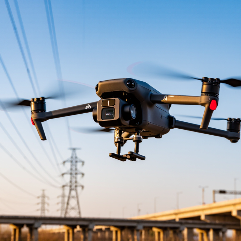
Choosing the right UAV camera module starts with the mission, not the camera’s advertised resolution. Define what the aircraft must capture, from roof damage to crop stress or shoreline changes. A mapping task needs stable geometry and accurate positioning. An inspection task may require fine detail, strong contrast, or thermal data. Ask how far the camera will operate from the subject. Distance changes the needed focal length, sensor size, and image resolution.
Operating conditions can quickly expose weak specifications. Bright snow, deep shadows, dust, vibration, and sudden temperature changes all affect image quality. Check the sensor’s dynamic range for scenes with harsh sunlight. Confirm the lens can maintain focus at the expected altitude. For night work, evaluate noise instead of trusting sample images. A sealed housing may help in light rain, but it cannot replace proper flight planning or local operating rules.
Field testing remains essential. I once selected a sharp camera that produced blurred frames during fast turns. The problem was vibration, not resolution. Mount stiffness, shutter speed, weight, and power demand must be checked together. Record sample footage at real speed and altitude. Examine small text, moving edges, and dark areas frame by frame. Leave room for mistakes. Weather changes, batteries weaken, and operators sometimes misjudge glare. A reliable module is one that still delivers usable evidence when conditions are less than ideal.
Compare Sensor Types, Resolutions, and Image Quality
Choosing a UAV camera module starts with the sensor, not the advertised megapixel count. CMOS sensors offer low power use and strong detail for most aerial mapping tasks. A global shutter captures the whole frame together. It reduces leaning on moving objects during fast flight. Rolling shutters can create skew, especially during sharp turns. That issue is easy to miss in a calm test.
Resolution should match the flying height and target size. A 20-megapixel sensor may help identify roof damage, but it cannot fix poor focus or motion blur. Pixel size also matters. Larger pixels usually collect more light and produce cleaner shadows. For bright farmland, a standard RGB sensor may be enough. Thermal or multispectral sensors reveal heat and vegetation patterns that visible light cannot show. Choose them only when the project needs those measurements.
Image quality depends on more than sharp corners. Check dynamic range, color accuracy, lens distortion, frame rate, and image format. A 12-bit file can preserve subtle details in a bright roof and dark doorway. Keep the lens clean. It sounds obvious. In field trials, vibration often damaged results more than sensor noise. I once trusted a high-resolution sample that looked excellent on screen. Later, motion blur weakened the measurements. Now I inspect raw images, ground details, and repeated flight strips before approving a module. A reliable choice balances sensor behavior, resolution, lighting, and real flight limitations.
When choosing a UAV camera module, examine the lens before comparing megapixels. A wide field of view captures more terrain, but distant objects appear smaller. A narrow field of view provides stronger visual detail, yet it can miss nearby movement. Check edge distortion, aperture, and low-light performance in real flight conditions. In field tests, a lens with slight distortion may still outperform a sharper lens during fast turns. My early selections focused too much on resolution. The footage looked impressive, but important details near the frame edges were stretched.
Tips:
Stabilization must match the aircraft’s vibration profile and flight purpose. A mechanical gimbal usually produces smoother footage during acceleration and sudden direction changes. Electronic stabilization can reduce small shakes, but it may crop the image and narrow the usable field of view. Check whether stabilization changes framing during turns. Also test rolling-shutter distortion near spinning propellers or fast ground movement. A stable image is not always a natural image. Too much correction can make straight lines appear to breathe. Before installation, compare the module’s weight, mounting flexibility, and vibration isolation with the aircraft. Small differences can affect endurance and image consistency.
Choosing the right UAV camera module starts with aircraft compatibility, not image resolution. Check the mounting pattern, available clearance, and gimbal limits before comparing sensors. A camera that fits on a workbench may still interfere with landing gear or propeller airflow.
Weight matters in the air. A heavier module can shorten flight time and make the aircraft less stable in wind. Measure the complete payload, including cables, brackets, and vibration dampers. Power requirements also deserve careful testing. Confirm voltage, peak current, and startup behavior with the flight controller. I once underestimated cable loss, and the camera restarted during rapid altitude changes. That mistake was avoidable.
Tips: Leave a small weight margin. Test every connector. Record flight time before and after installation.
Data interfaces should match the aircraft’s onboard computer and storage system. Common options may include Ethernet, USB, serial links, or specialized video connections. Check bandwidth, connector type, cable length, and software support. A high-resolution stream is useless if the interface drops frames or creates excessive heat. Use short, secured cables near moving parts. Bench tests help, but real flight tests reveal vibration, temperature, and signal problems. Do not assume identical connectors provide identical performance; specifications can be incomplete, and practical testing remains necessary.
Compare typical module weight, power consumption, and required data-interface bandwidth before selecting a camera for your UAV platform.
The values represent realistic engineering ranges for common UAV camera categories. Compact RGB modules generally require less payload capacity and power, while stabilized, thermal, and multispectral systems require stronger compatibility, higher power budgets, and faster data interfaces.
Choosing a UAV camera module starts with reliability, not pixel count. The 2024 Drone Industry Insights Drone Market Report projects strong commercial drone growth through 2030. That growth increases pressure on operators to select durable, upgradeable equipment. In field work, vibration, dust, heat, and sudden lighting changes expose weak designs quickly. Choose a sealed housing, secure connectors, and tested vibration resistance. Check the operating temperature range, not only the laboratory specification. A higher resolution number is not automatically safer.
Safety depends on predictable images. A camera with wide dynamic range can preserve detail near bright skies and dark ground. Low-light performance also matters during dawn inspections. Global shutter technology can reduce distortion when the aircraft moves quickly. The FAA reported more than 800,000 registered drones in the United States by the end of 2023, showing how widely these systems are entering operational environments. That scale makes consistent imaging and maintenance records more important. Select modules with stable firmware, diagnostic reporting, and clear power requirements. Keep the camera below the aircraft’s available power margin. Small errors become serious during long flights.
Future upgrades need open interfaces and documented software support. A standard video output, accessible control protocol, and replaceable lens options can extend service life. Thermal imaging, depth sensing, or onboard processing may become useful later. However, adding every feature today can increase weight, heat, and failure points. I would leave expansion capacity, but avoid buying complexity without a mission need. The EASA Annual Safety Review continues to identify technical failures and loss of control as recurring safety concerns. Test the complete payload under real vibration and temperature conditions. Laboratory confidence can be misleading.
„Thanks to the LUVIR technology, the solder resist process could be switched directly from the previously used mask exposure to direct exposure. As an outstanding digital solution on the market, this technology has been able to demonstrate fast process times and superior quality on our certified conventional ink in production. This allowed us to fully digitize the solder mask process at low cost – without process or ink adjustments. An excellent benefit to our production in Rot am See.“
Ralf Göhringer (Head of Production WE Rot am See)
I would definitely recommend the Limata machine and team for a future company purchase
Michael Greenaway
Compunetics Inc.
“The Limata ldi has been amazing!! Best thing we did was buy this machine”
Richard Brady
GM
Circuitlabs
“Since 2019, we have been running the Limata X1000 LDI system (including LUVIR for solder mask imaging) in daily production as an addition to our current process with film. The machine was capable of properly exposing Taiyo PSR-4000 BN (DI) solder mask types on normal to high-copper boards using a new and unique direct imaging process. The machine operating interface is very user friendly which allowed for a quick technical training curve. The pre-registration processing reduced several seconds of production time at every print. Limata support and service staff is incomparable. They supported our team every step of the way at basically any time of the day or night, with literally, an immediate response time, customizing the software interface to best fit our Operations and needs.
We have exposed more than 8,000 prints since end of October, on various solder mask colors and some resist film panels. Limata, has proven to be very capable and innovative. They are a strong contender in the industry.
We have very much enjoyed this project, and working with the team!
Thank you Limata for the continued support and being a part of our growth.”
Bill Sezate
Vice President, GM
Summit Interconnect
As a replacement to our current contact exposure process with film, the LIMATA X2000 system including LUVIR-Technology was capable of properly exposing non-LDI solder mask types using a direct imaging process. The machine offers cutting edge software with a very intuitive operating interface which allowed for quick technician training curve. The dual drawer system combined with pre-registration processing reduced several seconds of production time at every machine cycle. Limata support and service staff is world class. They added software patches to keep production running at shortest possible response times, customized the software interface to best fit our in-house Operations system, and even wrote a step-by-step machine processing manual. As a result of the project, we have exposed more than 16,000 times on various product types and solder mask brands/colors. Limata, in a very short timeframe as a company, has definitely shown they are truly innovative and will be challenging the industry of direct imaging for the top spot.
Kevin Beattie
Process Engineer
TTM Technologies
Forest Grove Division