Every reliable water network depends on small components that rarely receive public attention. A Dismantling Joint is one of them. It connects flanged pipes while allowing controlled axial movement during installation, maintenance, or valve replacement. Its threaded or flanged adjustment mechanism can separate equipment without cutting the pipeline. That practical function matters beneath roads, treatment plants, and industrial floors.
The World Health Organization and UNICEF reported that 2.2 billion people lacked safely managed drinking water services in 2022. This figure exposes a wider challenge: water infrastructure must remain serviceable, not merely installed. The American Society of Civil Engineers rated America’s drinking water infrastructure at C-minus in its 2021 Infrastructure Report Card. Aging pipes, restricted access, and unplanned shutdowns can turn a minor repair into a disruptive excavation.
Water expert Peter Gleick has described water as “the lifeblood of the planet.” His observation gives this mechanical component a larger context. A Dismantling Joint protects continuity around critical assets, including pumps, gate valves, meters, and non-return valves. Installers can adjust the joint’s length, align flanges, and remove equipment with fewer structural changes. The exact benefit depends on correct sizing, bolt tightening, gasket selection, and restrained-pipe design.
It is not maintenance-proof.
Designers should check pressure ratings, movement limits, corrosion exposure, and manufacturer instructions. Standards such as AWWA C219 can support specification decisions, but site conditions still demand engineering judgment. A joint may look simple. Its failure consequences are not. Even strong products perform poorly when alignment, torque, or support details are overlooked. This article explains what a Dismantling Joint is, how it works, and where its limitations deserve closer attention.
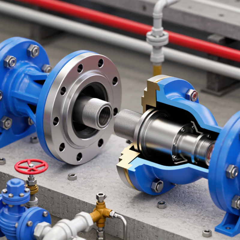
A dismantling joint is a flanged pipe fitting that allows controlled separation between connected pipeline components. It usually includes a central flange body, sealing gasket, adjustable flange, and tie rods. During installation, technicians set the joint to match the pipe gap. After tightening, the tie rods maintain the required length and alignment.
Its pipeline role is practical, not decorative. It creates working space around valves, pumps, flow meters, and other heavy fittings. When maintenance begins, engineers can loosen the joint and withdraw the component without cutting the pipe. This reduces downtime and limits damage to nearby coatings.
The joint must also resist internal pressure and external loads. However, it should not be treated as a universal expansion device. Pressure thrust still requires suitable anchors, restraints, or structural support.
The need for maintainable networks is growing. The U.S. Environmental Protection Agency’s 2023 Drinking Water Infrastructure Needs Survey estimated $625 billion in investment needs over 20 years. The WHO and UNICEF Joint Monitoring Programme reported that 2.2 billion people lacked safely managed drinking water in 2022. These figures do not measure dismantling joints directly, but they show why repair-ready pipeline design matters. A practical inspection lesson is often overlooked: incorrect tie-rod adjustment can create flange stress or leakage. Small errors matter. Designers should verify bolt loads, gasket compatibility, pipe alignment, and access clearance before commissioning. Industry standards help, but site conditions still demand judgment.
A dismantling joint connects flanged pipes, valves, pumps, and other equipment. It allows controlled length adjustment during installation or removal. Its main parts are flanges, tie rods, and a sealing gasket. The flanges create a firm connection between pipe ends. The gasket fills tiny surface gaps and prevents leakage. Tie rods hold the assembly together and transfer axial forces during service.
PN10–PN25 ratings describe nominal pressure classes, usually from 10 to 25 bar under reference conditions. They are not automatic guarantees for every application. Temperature, fluid type, flange standard, bolt quality, and gasket material can change the safe working pressure. A PN25 joint may perform poorly if the connected pipe system lacks proper anchoring. This detail is often underestimated. During field inspections, uneven bolt tightening is a common cause of gasket damage and flange distortion. A clean drawing can still hide installation problems.
Tips: Confirm the pipe’s outside diameter before ordering. Check flange drilling, gasket compatibility, and tie-rod clearance. Tighten bolts gradually in a cross pattern. Leave enough adjustment space for future valve removal. Never treat the tie rods as a substitute for structural supports. Record the final bolt torque and alignment. Small records help later, although teams sometimes skip them under schedule pressure.
What Is a Dismantling Joint and How Does It Work?
A dismantling joint connects flanged pipes while allowing controlled length adjustment during installation. Its main value appears when pipe ends do not meet perfectly. A typical unit provides about 50 mm of axial adjustment, depending on the design and pipe diameter. That range can absorb small construction errors without forcing the flange, valve, or pump into position.
Measure twice. Keep it square.
Before tightening, installers should clean both flange faces and inspect the gasket seating area. The pipe should be supported independently, so the joint does not carry unexpected bending loads. Workers then loosen the tie rods, position the joint within its adjustment range, and bring the flanges together evenly. A steel rule or laser level helps check the gap around the circumference. Uneven gaps often signal pipe misalignment, not a gasket problem.
Torque matters, but sequence matters more. Bolts should be tightened in a diagonal pattern, using calibrated equipment and the project specification. The U.S. EPA’s 2023 7th Drinking Water Infrastructure Needs Survey and Assessment estimated a 20-year drinking water infrastructure need of about 625 billion dollars. That figure shows why maintainable connections matter. A joint that saves hours during valve replacement can reduce shutdown exposure and labor pressure. Still, 50 mm is not permission to pull a pipe into place. That shortcut may work once, but it can transfer stress into nearby supports. The installation may look acceptable today. It may not remain so after pressure cycles.
What Is a Dismantling Joint and How Does It Work?
Operating Principle: Sealing, Axial Movement, and Load Transfer in Service
A dismantling joint connects flanged pipe sections while allowing controlled axial adjustment. Its central body usually includes a flange, sealing gasket, telescopic sleeve, and restraint components. During installation, the sleeve moves along the pipe axis. This movement creates space for valve replacement, pump removal, or flange alignment. It is practical, not unlimited.
The gasket seals when the flanges compress it evenly around the pipe bore. Correct bolt tightening produces contact pressure across the gasket surface. Poor alignment can create a narrow leak path on one side. Field technicians should check flange faces, gasket position, and bolt sequence before pressurizing the line. Small installation errors matter.
Internal pressure creates axial thrust at changes in diameter, closed ends, and connected equipment. Tie rods or other restraint members transfer this force through the joint and into the surrounding pipeline system. The joint must resist service loads without losing gasket compression. However, it should not be treated automatically as a thermal expansion joint. Allowable movement, pressure, temperature, and load capacity depend on the design. A common mistake is assuming every dismantling joint performs identically. Site conditions may prove otherwise. Regular inspection should look for corrosion, displaced bolts, gasket seepage, and unusual sleeve movement.
What Is a Dismantling Joint and How Does It Work?
A dismantling joint connects flanged pipes, valves, and other equipment. Its telescopic body allows controlled length adjustment during installation or removal. Tie rods hold the assembly together and resist pressure-related movement. They do not replace proper pipe supports or thrust restraint. That distinction matters.
Safe removal begins with isolation, depressurization, and drainage. A pressure gauge reading is not enough. Technicians should verify zero pressure through an approved vent or drain point. The pipeline must also be supported before any tie-rod nut is loosened. Otherwise, the joint may shift suddenly, even when the pipe appears stable. It can move.
After checking alignment, crews mark the original flange position and measure the joint gap. They loosen tie-rod nuts gradually, using a crosswise pattern. This releases stored restraint more evenly. The joint can then be retracted slightly, creating working clearance without cutting the pipeline. Lifting equipment should support heavy valves or pipe sections during this step. Never rely on the tie rods as lifting points unless the design specifically allows it.
The process sounds simple, but site conditions often complicate it. Corrosion can hide damaged threads, and trapped liquid may remain inside a low section. A careful inspection may reveal problems before removal begins. The joint should be examined for distorted flanges, bent rods, and damaged seals. If the measured gap differs greatly from installation records, stop and reassess the pipe supports, alignment, and restraint calculations. Mistakes here are quiet at first, then expensive.
A dismantling joint uses adjustable tie rods to restrain axial forces while allowing a flanged pipeline section, valve, or fitting to be safely removed without cutting the pipe. The chart shows the theoretical pressure thrust for a 300 mm internal pipe diameter at different operating pressures, calculated using F = P × A.
Values are calculated engineering examples for a closed pipe end and exclude friction, fittings, temperature effects, and other installation factors. Final tie-rod sizing and removal procedures must be verified by a qualified engineer.
„Thanks to the LUVIR technology, the solder resist process could be switched directly from the previously used mask exposure to direct exposure. As an outstanding digital solution on the market, this technology has been able to demonstrate fast process times and superior quality on our certified conventional ink in production. This allowed us to fully digitize the solder mask process at low cost – without process or ink adjustments. An excellent benefit to our production in Rot am See.“
Ralf Göhringer (Head of Production WE Rot am See)
I would definitely recommend the Limata machine and team for a future company purchase
Michael Greenaway
Compunetics Inc.
“The Limata ldi has been amazing!! Best thing we did was buy this machine”
Richard Brady
GM
Circuitlabs
“Since 2019, we have been running the Limata X1000 LDI system (including LUVIR for solder mask imaging) in daily production as an addition to our current process with film. The machine was capable of properly exposing Taiyo PSR-4000 BN (DI) solder mask types on normal to high-copper boards using a new and unique direct imaging process. The machine operating interface is very user friendly which allowed for a quick technical training curve. The pre-registration processing reduced several seconds of production time at every print. Limata support and service staff is incomparable. They supported our team every step of the way at basically any time of the day or night, with literally, an immediate response time, customizing the software interface to best fit our Operations and needs.
We have exposed more than 8,000 prints since end of October, on various solder mask colors and some resist film panels. Limata, has proven to be very capable and innovative. They are a strong contender in the industry.
We have very much enjoyed this project, and working with the team!
Thank you Limata for the continued support and being a part of our growth.”
Bill Sezate
Vice President, GM
Summit Interconnect
As a replacement to our current contact exposure process with film, the LIMATA X2000 system including LUVIR-Technology was capable of properly exposing non-LDI solder mask types using a direct imaging process. The machine offers cutting edge software with a very intuitive operating interface which allowed for quick technician training curve. The dual drawer system combined with pre-registration processing reduced several seconds of production time at every machine cycle. Limata support and service staff is world class. They added software patches to keep production running at shortest possible response times, customized the software interface to best fit our in-house Operations system, and even wrote a step-by-step machine processing manual. As a result of the project, we have exposed more than 16,000 times on various product types and solder mask brands/colors. Limata, in a very short timeframe as a company, has definitely shown they are truly innovative and will be challenging the industry of direct imaging for the top spot.
Kevin Beattie
Process Engineer
TTM Technologies
Forest Grove Division