An Electric Crucible Melting Furnace heats metal inside a removable crucible, using electric resistance or induction. The crucible holds the charge while the furnace brings it to a controlled melting temperature. Operators can then pour the liquid metal into a mould or transfer vessel. The setup may look simple: a glowing chamber, a crucible, and a pouring tool. Yet reliable results depend on careful temperature control, suitable crucible materials, and consistent handling.
John Campbell, a respected authority on metal casting, has emphasized the importance of controlling liquid metal quality. A practical summary of that principle—not a verbatim quotation—is: “Good castings begin with a well-controlled melt.” That idea helps explain why furnace choice matters. An Electric Crucible Melting Furnace can serve foundries, laboratories, and workshops processing different metals, but capacity, heating method, power supply, and operating temperature must match the task. Details matter. A cold crucible, uneven heating, or a rushed pour can affect the melt and the finished part. This guide explains how the furnace works, what its main components do, and which factors deserve attention before purchase. Not every application fits one furnace. Some decisions require testing with the actual metal, crucible, and mould. That limitation is worth acknowledging.
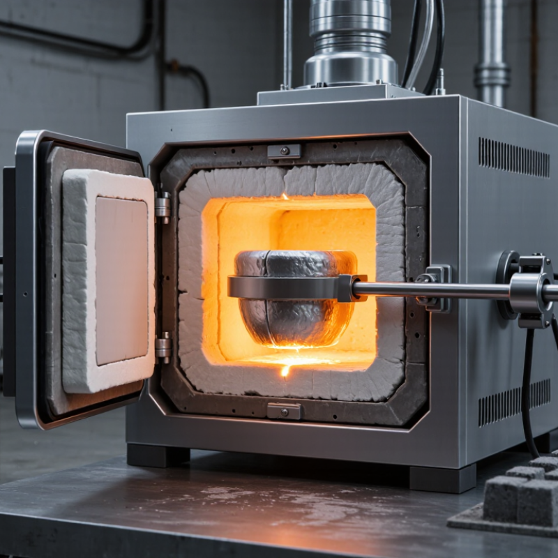
An electric crucible melting furnace heats material held inside a heat-resistant container called a crucible. Electricity produces heat around or within the crucible, depending on the furnace design. The charge may include metal or glass, but the crucible must suit the material and operating temperature. A temperature sensor and controller help regulate heating.
The furnace can melt a measured batch without a large fuel flame nearby. That can be useful in workshops, laboratories, and small foundries. The exact melting time varies with batch size, material, crucible condition, and power supply.
No single setting fits every job.
The operator typically checks the crucible for cracks, places the charge inside, and raises the temperature gradually. Small details matter. A temperature display does not show every hot or cool spot in the load.
In practice, the neat reading is not the whole story. Furnace capacity, ventilation, electrical requirements, and safe handling equipment all affect how the unit should be used. Heat-resistant gloves and a face shield help protect against radiant heat and splashes.
The furnace also needs a stable, suitable surface. It is easy to overestimate what a compact unit can melt; checking its rated capacity and material guidance before use is a sensible habit.
An electric crucible melting furnace uses electrical energy to heat metal inside a heat-resistant vessel. Its layout depends on whether it uses resistance heating or induction. The crucible holds the charge and must withstand high temperatures and contact with molten metal. Operators inspect it for cracks, thinning, and residue before use. Small defects matter.
In a resistance furnace, heating elements surround the chamber and transfer heat to the crucible. An induction model uses a coil to create a changing magnetic field, heating suitable metal charges directly.
A refractory lining reduces heat loss and protects the outer shell. The power supply regulates energy, while a controller and temperature sensor help maintain the selected range. Sensor readings may lag behind the metal’s actual temperature, so operators also consider soak time and the melt’s appearance. A lid limits heat loss and exposure to airborne debris. Some units have a tilting frame or pouring spout to guide the melt into a mold. These parts need regular checks; a clean-looking pivot can still bind under load. A stable pouring path matters.
What Is an Electric Crucible Melting Furnace?
How the Furnace Heats and Melts Metal
An electric crucible melting furnace uses electrical energy to bring metal to its melting point inside a heat-resistant container. In an induction furnace, a coil creates an alternating magnetic field around the crucible. This induces currents in conductive metal, heating the charge from within. In a resistance-heated furnace, electric elements warm the chamber; heat then passes through the crucible into the metal. The method matters. It affects melt speed, temperature uniformity, and energy use.
As metal warms, solid pieces soften and eventually form a liquid bath. NIST Chemistry WebBook data places aluminum’s melting point at about 660°C and copper’s at about 1,085°C. Operators monitor temperature and hold time, since an uneven charge can leave cooler material near the crucible wall. It is not instant. The U.S. Department of Energy reports that process heating accounts for about 68% of manufacturing energy use; that figure covers many processes, not crucible furnaces alone. A well-matched furnace, charge size, and power setting can reduce avoidable heating time. Still, temperature readings and actual melt conditions may differ, so operating decisions need care.
| Topic | How It Works | Practical Details |
|---|---|---|
| Basic definition | An electric crucible melting furnace uses electrical energy to heat a refractory or conductive crucible containing metal until the charge melts. | The crucible holds the metal and helps contain it during heating and pouring. |
| Resistance heating | Electric current passes through resistance elements, which become hot. Heat transfers from the elements to the furnace chamber, crucible, and metal. | The metal is heated mainly by heat transfer from the hot crucible and surrounding furnace chamber. |
| Induction heating | An alternating current in a coil creates a changing magnetic field. This induces electrical currents in conductive metal, generating heat within the charge. | The crucible must be compatible with the furnace design and metal being melted; some induction furnaces use a refractory lining rather than a separate removable crucible. |
| Melting sequence | The charge is loaded, power is applied, and the metal warms to its melting range. After melting, the operator may hold the bath at a controlled temperature before pouring. | Temperature control and a suitable holding time help support consistent pouring and reduce unnecessary overheating. |
| Aluminum melting point | Pure aluminum melts at approximately 660.3°C (1220.5°F). | Alloy composition changes the melting range, so the pure-metal value is a reference rather than a universal process setting. |
| Copper melting point | Pure copper melts at approximately 1084.6°C (1984.3°F). | Crucible and furnace materials must be rated for the temperatures and chemical conditions involved. |
| Zinc melting point | Pure zinc melts at approximately 419.5°C (787.1°F). | Zinc can produce hazardous fumes when overheated; appropriate ventilation and process controls are essential. |
| Crucible selection | Crucibles are selected according to the metal, operating temperature, furnace type, and potential chemical reactions. | Common materials include graphite, clay-graphite, silicon carbide, and ceramic refractories; suitability depends on the application. |
| Key operating factors | Performance depends on furnace power, charge size, metal properties, insulation, crucible condition, and the temperature-control method. | Actual melting time and energy use vary by equipment and operating conditions; they cannot be determined from furnace type alone. |
| Safety essentials | Molten metal presents severe burn and fire hazards. Moisture contacting molten metal can cause violent splashing or steam explosions. | Use dry charge and tools, suitable protective equipment, guarding, and ventilation, and follow the furnace manufacturer's operating instructions. |
An electric crucible melting furnace heats metal inside a heat-resistant container called a crucible. Common designs include stationary, tilting, and lift-out models. A stationary furnace suits repeatable small-batch work, while a tilting model pours by rotating its body. Lift-out designs let operators remove the crucible for pouring. Each arrangement changes how metal is handled, so consider pour height and access before choosing.
Heating methods vary. Resistance furnaces use electric elements to heat the chamber, which then warms the crucible and its contents. Induction models create electromagnetic currents that heat suitable conductive metal directly. They can respond quickly, but performance depends on the charge, crucible, and furnace setup. In practice, design categories sometimes overlap. That can make comparisons less tidy than brochures suggest.
Tips: Check that the crucible material suits both the metal and the heating method. Keep it dry, inspect it for cracks, and follow the equipment maker’s preheating guidance. Watch temperature readings during a melt; a sensor may not show every hot or cool spot. Small checks matter.
An electric crucible melting furnace heats metal inside a removable, heat-resistant vessel. Foundries use it for small batches of nonferrous alloys, including aluminum, brass, and bronze. It suits prototype work, repair shops, and production runs where flexible changeovers matter. Small batches matter. Operators can adjust temperature and pour without committing to a large melt, though manual handling still affects consistency.
The choice of crucible depends on alloy chemistry, peak temperature, and contamination risk. Charge pieces should be clean, dry, and sized for even heating. Power settings, melt time, and holding temperature influence energy use and metal loss. The U.S. Department of Energy’s Energy and Environmental Profile of the U.S. Metalcasting Industry identifies melting as a major energy-consuming foundry process. The International Aluminium Institute reports that recycling aluminum can use about 95% less energy than producing primary aluminum. That figure describes the recycling route, not one furnace’s efficiency. Not always. A tight lid may reduce heat loss, but poor maintenance or an unsuitable crucible can erase expected gains. Track electricity per kilogram, temperature stability, and rejected castings; the last measure is easy to overlook.
„Thanks to the LUVIR technology, the solder resist process could be switched directly from the previously used mask exposure to direct exposure. As an outstanding digital solution on the market, this technology has been able to demonstrate fast process times and superior quality on our certified conventional ink in production. This allowed us to fully digitize the solder mask process at low cost – without process or ink adjustments. An excellent benefit to our production in Rot am See.“
Ralf Göhringer (Head of Production WE Rot am See)
I would definitely recommend the Limata machine and team for a future company purchase
Michael Greenaway
Compunetics Inc.
“The Limata ldi has been amazing!! Best thing we did was buy this machine”
Richard Brady
GM
Circuitlabs
“Since 2019, we have been running the Limata X1000 LDI system (including LUVIR for solder mask imaging) in daily production as an addition to our current process with film. The machine was capable of properly exposing Taiyo PSR-4000 BN (DI) solder mask types on normal to high-copper boards using a new and unique direct imaging process. The machine operating interface is very user friendly which allowed for a quick technical training curve. The pre-registration processing reduced several seconds of production time at every print. Limata support and service staff is incomparable. They supported our team every step of the way at basically any time of the day or night, with literally, an immediate response time, customizing the software interface to best fit our Operations and needs.
We have exposed more than 8,000 prints since end of October, on various solder mask colors and some resist film panels. Limata, has proven to be very capable and innovative. They are a strong contender in the industry.
We have very much enjoyed this project, and working with the team!
Thank you Limata for the continued support and being a part of our growth.”
Bill Sezate
Vice President, GM
Summit Interconnect
As a replacement to our current contact exposure process with film, the LIMATA X2000 system including LUVIR-Technology was capable of properly exposing non-LDI solder mask types using a direct imaging process. The machine offers cutting edge software with a very intuitive operating interface which allowed for quick technician training curve. The dual drawer system combined with pre-registration processing reduced several seconds of production time at every machine cycle. Limata support and service staff is world class. They added software patches to keep production running at shortest possible response times, customized the software interface to best fit our in-house Operations system, and even wrote a step-by-step machine processing manual. As a result of the project, we have exposed more than 16,000 times on various product types and solder mask brands/colors. Limata, in a very short timeframe as a company, has definitely shown they are truly innovative and will be challenging the industry of direct imaging for the top spot.
Kevin Beattie
Process Engineer
TTM Technologies
Forest Grove Division
