Pneumatic automation depends on small connections that must perform reliably under pressure. Festo Pneumatic Connectors link tubing to valves, cylinders, filters, and other air-handling components. Their common push-in design uses a precision collet, sealing ring, and threaded body. Push the tube inward. The seal grips it. To release it, press the collet while pulling the tube.
This simple action hides important engineering decisions. Tube material, outside diameter, thread standard, pressure rating, temperature, and installation space all influence connector performance. Festo’s product documentation provides selection data for working pressure, media, tubing compatibility, and permitted environmental conditions. These details matter more than appearance. A fitting that feels secure may still leak because the tube was cut unevenly or inserted too shallowly.
Industry reports show why these components deserve closer attention. Grand View Research has estimated the global pneumatic components market at more than USD 14 billion in the early 2020s, with continued growth expected through the decade. MarketsandMarkets also identifies factory automation and manufacturing efficiency as major demand drivers. However, market figures vary between reports because product categories and regional definitions differ. That distinction matters.
In practical maintenance work, a small leak can sound like a faint hiss near a machine guard. It can also increase compressor demand and reduce actuator consistency. ISO 14743 provides an important reference for push-in fluid-power connectors, but standards do not replace correct installation. This guide explains how Festo Pneumatic Connectors work, where they fit in a pneumatic circuit, and how to assess their reliability. Some applications remain less obvious. Careful verification is still necessary.
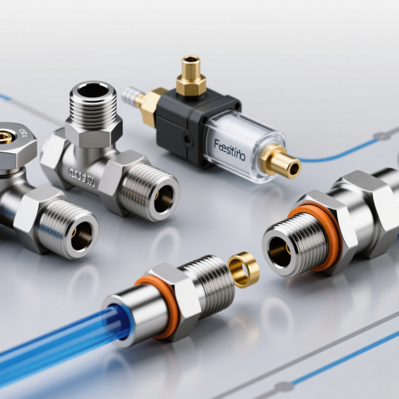
Pneumatic connectors are small components that join tubes, valves, cylinders, and manifolds in compressed-air systems. They guide air through a sealed path while allowing equipment to be assembled, adjusted, or replaced. Common designs include push-in fittings, threaded adapters, elbows, tees, and bulkhead connectors. A push-in model usually uses a gripping collet and an internal seal. The tube enters the fitting, and pressure helps maintain the seal during operation.
Connector selection depends on tube outside diameter, thread standard, working pressure, temperature, vibration, and air quality. ISO 14743:2020 specifies requirements for push-in connectors used with thermoplastic tubes. That matters because similar-looking threads may not match. The wrong seal material can also harden under heat or chemical exposure. Small detail. Big consequences.
The U.S. Department of Energy reports that compressed air can represent 10% to 15% of industrial electricity use, while leakage may waste 20% to 30% of compressor output in poorly maintained systems. A connector is not usually the largest energy user, but many minor leaks can become expensive. Field inspections often reveal loose threads, damaged tube ends, or incomplete insertion. A fitting may look secure and still leak. Product descriptions can make installation seem too simple. In practice, technicians should cut tubing squarely, verify insertion depth, and test connections at operating pressure.
Pneumatic connectors join compressed-air tubing to valves, cylinders, filters, and other air-powered components. Push-in designs use a collet to grip the tube and an internal seal to prevent air leakage. To disconnect the tube, press the release ring while pulling the tube straight out.
Chart guide: The chart shows common tube outside diameters used with push-in pneumatic connectors and representative minimum bend-radius values for flexible polyurethane tubing. Actual values vary with tube material, wall thickness, temperature, and operating pressure.
Pneumatic connectors join tubing to valves, cylinders, and air-preparation units. Their design begins with the tube, not the fitting. Engineers classify them by tube diameter, port thread, connection method, and airflow direction. Common types include push-in, compression, threaded, bulkhead, and swivel connectors. Push-in models use a gripping collet and an internal seal. They allow quick installation beside crowded machinery.
Materials also define performance. Nickel-plated brass handles pressure and repeated assembly well. Polymer bodies reduce weight and resist some chemical exposure. Stainless steel suits moisture, cleaning, and corrosive environments. ISO 14743 specifies requirements for push-in connectors used with thermoplastic tubes. Correct thread classification matters too. Metric, BSP, and NPT threads are not automatically interchangeable. A small mismatch can create a slow leak.
Leak control affects operating cost. The U.S. Department of Energy reports that compressed-air systems may waste 20–30% of their output through leaks and poor maintenance.
Connector selection therefore requires more than checking pressure ratings. Designers should verify temperature, tube hardness, seal material, vibration, and bend radius. A swivel fitting may reduce tube stress, but it can add another failure point. That trade-off is easy to overlook. Field technicians often find that a connector survives the pressure test but fails after thousands of machine cycles. The classification looks correct on paper. Reality is less tidy.
Pneumatic connectors join flexible tubes to valves, cylinders, filters, and manifolds. Their main task is simple: keep compressed air moving without leakage. In a push-in design, the tube passes through a release collar and reaches an internal stop. A collet grips the tube, while an elastomer seal presses around its outer wall. Air pressure usually strengthens the seal rather than opening it. A small detail matters. The tube must be cut squarely and inserted fully.
Inside an air system, the connector controls the transition between rigid ports and flexible tubing. When a valve opens, compressed air travels through the fitting into an actuator. The connector’s internal passage should avoid sharp restrictions, because pressure loss can slow cylinder movement. During exhaust, air reverses through the same passage and leaves through a silencer or valve outlet. The U.S. Department of Energy’s Improving Compressed Air System Performance guide reports that leaks can waste 20–30% of compressor output. That makes connector selection an energy issue, not only a mechanical one.
Technicians should check tube material, working pressure, temperature, thread form, and chemical compatibility. The seal may look intact but still leak after repeated bending or vibration. Not always obvious. The Compressed Air Challenge recommends regular leak surveys and pressure-drop checks across distribution systems. In practice, a simple listening test misses small leaks in noisy plants. Ultrasonic inspection is more reliable, though it adds time and training. I would not assume a connector is secure because it feels tight; a pull test and a soap-bubble check provide better evidence.
Pneumatic connectors join tubing to valves, cylinders, regulators, and air lines. Their push-in design uses an internal collet and seal to grip the tube. A clean, square tube cut is essential. Angled cuts can damage the seal or create a slow leak.
Before installation, isolate the air supply and release stored pressure. Cut the tube with a sharp cutter, not a knife or side cutters. Remove burrs and check the tube for scratches, flattening, or contamination. Push it fully into the connector until it reaches the internal stop. Then pull the tube gently by hand. It should resist movement without sliding out.
Threaded connections need careful handling. Apply an approved sealant only where the fitting design permits it, and keep sealant away from the tube opening. Tighten the connector with the recommended torque; excessive force may crack plastic bodies or distort metal threads. I once assumed a tight fitting was secure, but a damaged tube caused the actual leak. Small details matter.
Restore pressure gradually while watching the joint. Apply a suitable leak-detection solution and look for growing bubbles. Never test a suspected leak with your fingers. If leakage continues, depressurize the line and inspect the tube end, seal, and thread alignment. A connector may appear secure while vibration slowly loosens it, so record the inspection and recheck critical joints after initial operation.
Selecting the right pneumatic connector starts with the tube, not the fitting.
Measure the tube’s outside diameter with calipers. Then check thread size, port standard, pressure rating, and operating temperature.
Push-in connectors suit quick assembly, while threaded versions suit fixed installations.
Choose materials that resist oil, moisture, vibration, and cleaning chemicals.
Do not rely on appearance alone. A connector can look secure and still leak.
During installation, cut tubing squarely with a sharp cutter.
Remove burrs, insert the tube fully, and tug it gently.
Keep the tube free from side loads and sharp bends near the connection.
Use the recommended sealant on tapered threads, but never contaminate the air path.
Hand-tightening is often safer than excessive force.
Overtightening can crack plastic bodies or distort internal seals. That mistake is easy to make.
Inspect connections during routine machine checks.
Look for bubbles during a controlled leak test, brittle tubing, corrosion, or dust around the joint.
Replace damaged seals and tubes instead of repeatedly tightening the fitting.
Record recurring leaks; they may indicate vibration, incorrect sizing, or unstable pressure.
I still recheck selections after installation. Real machines expose assumptions that catalogs cannot.
„Thanks to the LUVIR technology, the solder resist process could be switched directly from the previously used mask exposure to direct exposure. As an outstanding digital solution on the market, this technology has been able to demonstrate fast process times and superior quality on our certified conventional ink in production. This allowed us to fully digitize the solder mask process at low cost – without process or ink adjustments. An excellent benefit to our production in Rot am See.“
Ralf Göhringer (Head of Production WE Rot am See)
I would definitely recommend the Limata machine and team for a future company purchase
Michael Greenaway
Compunetics Inc.
“The Limata ldi has been amazing!! Best thing we did was buy this machine”
Richard Brady
GM
Circuitlabs
“Since 2019, we have been running the Limata X1000 LDI system (including LUVIR for solder mask imaging) in daily production as an addition to our current process with film. The machine was capable of properly exposing Taiyo PSR-4000 BN (DI) solder mask types on normal to high-copper boards using a new and unique direct imaging process. The machine operating interface is very user friendly which allowed for a quick technical training curve. The pre-registration processing reduced several seconds of production time at every print. Limata support and service staff is incomparable. They supported our team every step of the way at basically any time of the day or night, with literally, an immediate response time, customizing the software interface to best fit our Operations and needs.
We have exposed more than 8,000 prints since end of October, on various solder mask colors and some resist film panels. Limata, has proven to be very capable and innovative. They are a strong contender in the industry.
We have very much enjoyed this project, and working with the team!
Thank you Limata for the continued support and being a part of our growth.”
Bill Sezate
Vice President, GM
Summit Interconnect
As a replacement to our current contact exposure process with film, the LIMATA X2000 system including LUVIR-Technology was capable of properly exposing non-LDI solder mask types using a direct imaging process. The machine offers cutting edge software with a very intuitive operating interface which allowed for quick technician training curve. The dual drawer system combined with pre-registration processing reduced several seconds of production time at every machine cycle. Limata support and service staff is world class. They added software patches to keep production running at shortest possible response times, customized the software interface to best fit our in-house Operations system, and even wrote a step-by-step machine processing manual. As a result of the project, we have exposed more than 16,000 times on various product types and solder mask brands/colors. Limata, in a very short timeframe as a company, has definitely shown they are truly innovative and will be challenging the industry of direct imaging for the top spot.
Kevin Beattie
Process Engineer
TTM Technologies
Forest Grove Division