Choosing a Pneumatic Punching Machine in 2026 requires more than comparing purchase prices. Production speed, material thickness, air consumption, tooling access, and operator safety must work together. Numbers matter. A machine that punches 60 strokes per minute may still underperform if its compressor cannot maintain stable pressure.
Industry forecasts provide useful direction, but they are not complete buying instructions. Fortune Business Insights reports continued expansion in the global metal stamping market, supported by automotive, electronics, and appliance production. Grand View Research also identifies automation and precision control as important growth factors in modern stamping equipment. These reports describe market movement, not the exact machine needed for your factory. That distinction is easy to miss.
A practical evaluation should begin with actual workpieces. Measure sheet thickness, hole diameter, stroke length, daily cycle volume, and acceptable noise levels. Then compare rated force, working pressure, throat depth, die compatibility, and maintenance access. ISO 12100-based risk assessment principles can support safer machine selection, while local requirements may also involve CE marking, OSHA rules, or other national standards. Ask suppliers for test samples, force charts, pneumatic diagrams, warranty terms, and documented spare-parts availability. A clear demonstration is more reliable than a polished brochure.
My experience suggests that buyers often overvalue maximum force. They sometimes overlook air quality, lubrication, and setup time. That is a costly weakness. A smaller machine may deliver better value when its tooling changes quickly and its compressor operates efficiently. No single report answers every question. This guide therefore combines published market evidence with practical inspection points, helping buyers choose equipment that fits real production conditions rather than impressive specifications alone.
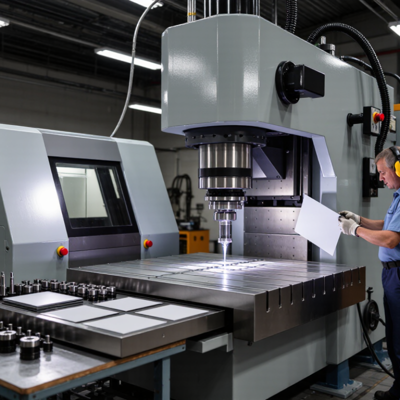
Start with the material and its actual thickness. The required punching force depends on the cutting perimeter, thickness, and shear strength. Use F = L × t × τ. Here, L is the cutting length, t is material thickness, and τ is shear strength. Keep units consistent. If a 20 mm round hole cuts 2 mm mild steel, L is about 62.8 mm. With a shear strength of 300 N/mm², the force equals 37,680 N, or 37.7 kN. That is roughly 3.8 metric tons before adjustment.
Do not size the machine from the basic result alone. Add a practical safety margin, often 30% to 50%, depending on production speed, tooling wear, and material variation. This example may need about 49 to 57 kN. Check the machine’s rated tonnage at the required stroke, not only its maximum rating. Air pressure also matters. A weak compressor can make a correctly calculated machine perform poorly. Die clearance, punch sharpness, and hole shape can change the real load.
In shop-floor checks, I have found that material labels are sometimes too general. “Steel” is not enough. Confirm the grade, thickness tolerance, and hardness when possible. Aluminum, stainless steel, and coated sheet behave differently.
I would also test one sample before regular production. My calculation may look precise, yet worn tooling or uneven clamping can still cause trouble. Leave room for that uncertainty. Safety guards, two-hand controls, and routine inspections should match the machine’s intended use.
Choosing a pneumatic punching machine starts with the part, not the catalog. Measure the material thickness, hole pattern, edge distance, and maximum workpiece width. Stroke should clear the material and complete the cut without excessive travel. A stroke that is too short leaves partial holes. Excessive stroke may slow cycling and increase tool wear. Keep a small safety margin.
Throat depth must reach the farthest hole from the sheet edge. For a 300-millimeter panel, a shallow throat can force awkward repositioning. That may create alignment errors. Check the frame opening and account for clamps, guards, and bent flanges. A practical trial with a scrap panel often reveals interference that drawings miss.
Die clearance controls cutting quality.
For mild steel, clearance commonly falls near 5–10% of material thickness per side, but alloys and thicknesses can change this range. Too little clearance raises force and damages edges. Too much clearance produces heavy burrs and distortion. Inspect the first holes for rollover, burr height, and slug shape. Air pressure and punch sharpness also matter. A clean result does not prove the setup is optimal. Recheck clearance after tool wear, because production conditions rarely remain perfectly stable.
How to Choose a Pneumatic Punching Machine in 2026?
When comparing pneumatic punching machines, begin with force and stroke, not catalog appearance. A 20–60 kN range covers light sheet work through thicker steel and repeated forming. At 0.6 MPa, producing 20 kN theoretically requires about a 65 mm bore. Producing 60 kN needs roughly a 113 mm bore. Seal friction and pressure losses reduce real output.
Stroke selection is equally important. A 30 mm stroke suits shallow holes and short cycle times. A 100 mm stroke provides more clearance for fixtures, layered materials, and deeper forming. It also consumes more air and may reduce operating speed. According to MarketsandMarkets, the global pneumatic equipment market is projected to grow at over 5% annually through the decade, increasing demand for efficient air systems. Efficiency matters.
Check the force at the actual end of the stroke. Some machines reach rated capacity only near the bottom position. That detail is easy to miss. ISO 4414 emphasizes safe pneumatic-system design, while ISO 6358 provides methods for evaluating airflow characteristics. Use those references when reviewing valve performance and compressor demand. A useful field check is simple: measure hole quality, cycle time, and pressure recovery during continuous operation. A 60 kN machine may sound safer, but excessive capacity can increase cost, air use, and tooling stress. I would question that choice.
How to Choose a Pneumatic Punching Machine in 2026?
A practical choice starts with the required production rhythm, not the advertised maximum speed. A machine rated at 30–80 strokes per minute may behave differently under real load. Material thickness, die clearance, feeding distance, and operator timing all affect output. For example, a 50 SPM setting produces one stroke every 1.2 seconds. That sounds fast, but frequent stops can reduce actual production by 15–25%. Leave working room.
Air consumption deserves closer attention. Check whether the specification states consumption per stroke, per cycle, or per minute. These figures are not interchangeable. If one cycle uses 0.8 liters of free air, 50 SPM requires about 40 liters per minute. Add a reserve of 20–30% for leakage, pressure drops, and occasional peak demand. A receiver tank supports short bursts, but it cannot replace adequate compressor capacity.
Select a compressor by free air delivery at the working pressure, not motor horsepower alone. A compressor delivering 60 L/min may struggle with a machine needing 50 L/min continuously. I have seen pressure fall during long runs because the calculation ignored other tools on the same air line. Use a clean, dry supply and verify the regulator near the machine. Record pressure and cycle rate during a real trial. The spreadsheet may still be wrong. Recheck it after production begins.
How to Choose a Pneumatic Punching Machine in 2026?
Verify ISO 12100 Safety, CE Compliance, and Automation Compatibility
A reliable pneumatic punching machine begins with a documented risk assessment. ISO 12100 provides a framework for identifying hazards and reducing risks through design. Ask for evidence covering crushing points, unexpected starts, noise, and stored pneumatic energy. Guards should block access during operation, while interlocked doors should stop the cycle immediately.
Do not treat a CE mark as a complete safety guarantee. Request the EU Declaration of Conformity, technical documentation, and applicable harmonized standards. Check whether the declaration matches the exact machine model and its electrical equipment. Test the emergency stop, pressure relief, and restart behavior before purchase. Small details matter.
Automation compatibility requires more than a PLC connection. Confirm input and output signals, sensor types, cycle timing, air pressure, and communication protocols. The machine should exchange clear status signals with conveyors, feeders, or robotic systems. Safety circuits must remain independent from ordinary control logic. A checklist can miss real production problems. Try a sample cycle using your material, tooling, and planned line speed. Document failures, even minor ones. They may reveal unstable sensing, slow exhaust, or inconsistent punching force. Reliable suppliers should answer technical questions clearly and provide test records. Vague promises deserve a second review.
„Thanks to the LUVIR technology, the solder resist process could be switched directly from the previously used mask exposure to direct exposure. As an outstanding digital solution on the market, this technology has been able to demonstrate fast process times and superior quality on our certified conventional ink in production. This allowed us to fully digitize the solder mask process at low cost – without process or ink adjustments. An excellent benefit to our production in Rot am See.“
Ralf Göhringer (Head of Production WE Rot am See)
I would definitely recommend the Limata machine and team for a future company purchase
Michael Greenaway
Compunetics Inc.
“The Limata ldi has been amazing!! Best thing we did was buy this machine”
Richard Brady
GM
Circuitlabs
“Since 2019, we have been running the Limata X1000 LDI system (including LUVIR for solder mask imaging) in daily production as an addition to our current process with film. The machine was capable of properly exposing Taiyo PSR-4000 BN (DI) solder mask types on normal to high-copper boards using a new and unique direct imaging process. The machine operating interface is very user friendly which allowed for a quick technical training curve. The pre-registration processing reduced several seconds of production time at every print. Limata support and service staff is incomparable. They supported our team every step of the way at basically any time of the day or night, with literally, an immediate response time, customizing the software interface to best fit our Operations and needs.
We have exposed more than 8,000 prints since end of October, on various solder mask colors and some resist film panels. Limata, has proven to be very capable and innovative. They are a strong contender in the industry.
We have very much enjoyed this project, and working with the team!
Thank you Limata for the continued support and being a part of our growth.”
Bill Sezate
Vice President, GM
Summit Interconnect
As a replacement to our current contact exposure process with film, the LIMATA X2000 system including LUVIR-Technology was capable of properly exposing non-LDI solder mask types using a direct imaging process. The machine offers cutting edge software with a very intuitive operating interface which allowed for quick technician training curve. The dual drawer system combined with pre-registration processing reduced several seconds of production time at every machine cycle. Limata support and service staff is world class. They added software patches to keep production running at shortest possible response times, customized the software interface to best fit our in-house Operations system, and even wrote a step-by-step machine processing manual. As a result of the project, we have exposed more than 16,000 times on various product types and solder mask brands/colors. Limata, in a very short timeframe as a company, has definitely shown they are truly innovative and will be challenging the industry of direct imaging for the top spot.
Kevin Beattie
Process Engineer
TTM Technologies
Forest Grove Division