Choosing an auto coupling circuit in 2026 starts with the job it must perform. Will it transfer power, connect signals, or isolate two sections of a vehicle system? These needs call for different circuit designs. The phrase Coupling Circuit Auto can describe several applications, so confirm what the product connects before comparing options. A part that fits the connector may still be electrically unsuitable.
Check the vehicle’s operating voltage, expected current, load behavior, and signal requirements against the manufacturer’s datasheet. Then consider the conditions around the circuit. A unit near an engine may face heat, vibration, moisture, and electrical transients that a cabin-mounted unit does not. Inspect connector type, pin layout, wire gauge, and available mounting space. Small details matter. So does the fuse rating.
For dependable selection, compare documented operating limits and test evidence, not just a product description. Look for relevant automotive qualification information, and verify that it matches your vehicle and installation. If the circuit is safety-critical, ask a qualified automotive engineer or technician to review the design. Don’t guess. One limitation is easy to miss: catalog ratings may not describe performance under every real-world condition. This guide explains the key checks, trade-offs, and questions to ask before choosing an auto coupling circuit. It also points out where a careful second review can prevent an expensive mismatch.
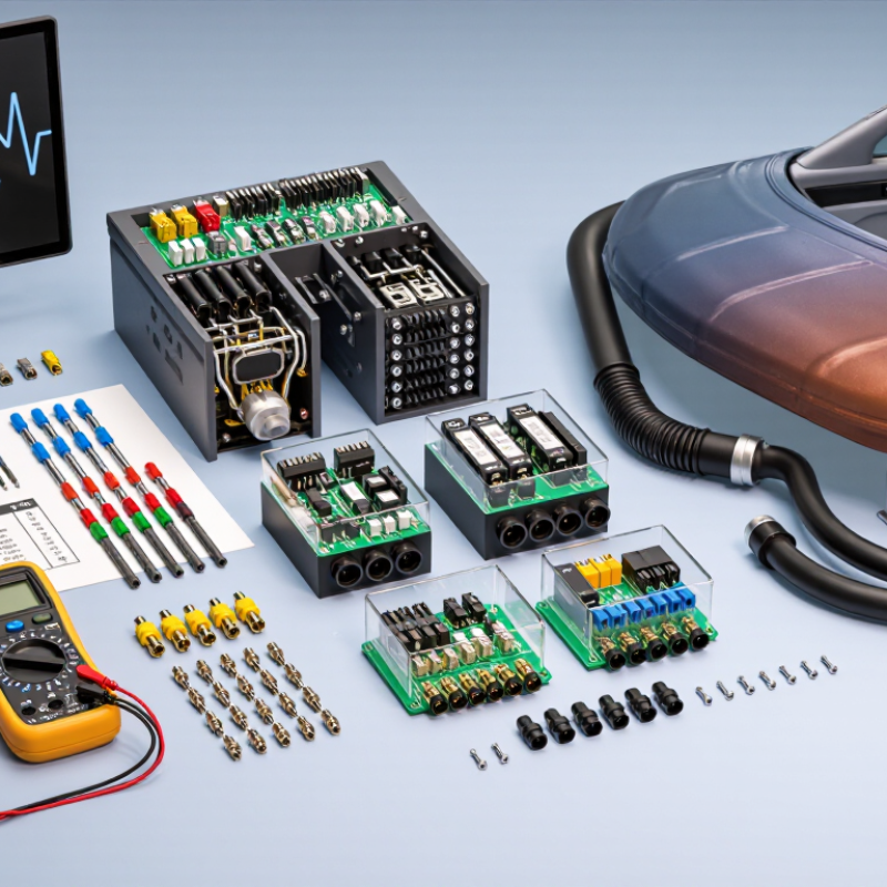
Before selecting an auto coupling circuit, define its job. Is it linking a starter battery to an auxiliary battery, feeding a trailer, or isolating two power sources? The answer determines the required current, switching method, and protection. A circuit intended only for a small control signal may fail when asked to carry starter-level current. Check the load rating, cable size, fuse location, and whether the circuit must connect only while the engine runs.
Then match the circuit to the system’s nominal voltage. A 12 V lead-acid system commonly charges around 13.8–14.7 V; a 24 V system operates at roughly twice that range. Bosch Automotive Handbook, 10th edition, describes these charging-system ranges, while ISO 16750-2:2023 addresses electrical-load testing for road-vehicle components. Use those references to check operating and test-voltage limits, not as substitutes for the vehicle’s wiring diagram. A 12 V relay coil on a 24 V system can overheat. A 24 V coil on 12 V may not pull in reliably. Small mismatch, big trouble.
Confirm the vehicle’s actual voltage at the battery posts with a meter, both engine-off and running. Some equipment uses a 12 V branch in a 24 V vehicle, so the vehicle label alone may not settle the question. Check the circuit diagram and component markings. A label can still mislead. Recheck polarity, ground path, and transient protection before installation.
Choosing an automotive coupling circuit starts with its electrical environment, not a convenient nominal voltage. ISO 16750-2 describes electrical-load tests for road-vehicle equipment, including supply-voltage variations, interruptions, and reverse-voltage conditions. Check the applicable edition and vehicle-specific requirements before setting test levels; one profile may not fit every installation. Record normal operating voltage, brief dips, and possible surges, then verify that the circuit remains functional or fails safely as required.
Temperature needs separate attention. ISO 16750-2 does not define the main temperature test profiles; ISO 16750-4 covers climatic loads. Set the expected temperature range from the mounting location, such as a shaded cabin panel or a hot engine-bay bracket, and account for heat generated by nearby components. Heat changes everything. Test the coupling circuit at relevant temperature extremes while applying its specified electrical loads, since contact resistance and insulation performance can shift with temperature. Leave margin where measurements are uncertain. Real installations are rarely as tidy as a lab setup, and that deserves a second look.
How to Choose an Auto Coupling Circuit in 2026
Check Electrical Transient Immunity Against ISO 7637-2 Tests
An auto coupling circuit must handle more than steady battery voltage. Road vehicles can expose power lines to fast transients from switching loads, wiring inductance, and supply interruptions. ISO 7637-2 defines test pulses for electrical disturbances on vehicle supply lines. Check which pulses, severity levels, and test conditions apply to your installation; requirements can vary by vehicle specification and system design.
Do not choose protection from a component’s peak-voltage figure alone. Review its clamping behavior, energy rating, response time, and interaction with downstream electronics. Then test the complete circuit under the relevant pulses, with realistic cable lengths and operating loads. Monitor both the protected voltage and whether the device resets, misbehaves, or loses function. A circuit may pass a pulse once and still perform poorly during repeated exposure. That detail is easy to miss.
Tips: Confirm test setup and pulse polarity before testing. Record waveforms at the circuit input and protected output. Keep notes on failures, even minor ones; a brief reset can matter in real use. Recheck the design after layout changes, since trace length and grounding can alter transient paths.
Transient duration varies widely across ISO 7637-2 pulse types. Use this comparison to plan coupling-circuit bandwidth and test coverage; verify pulse amplitudes, source impedance, and setup against the applicable standard edition and test severity.
Representative waveform durations: Pulse 1 ≈ 2 ms; Pulse 2a ≈ 50 μs; Pulse 3a/3b ≈ 100 ns; Pulse 4 ≈ 300 ms. Pulse 5 load-dump duration varies, so the chart uses 100 ms as an example within the commonly specified 40–400 ms range. Exact test parameters depend on the applicable edition, severity level, and test conditions.
How to Choose an Auto Coupling Circuit in 2026
Begin with the vehicle-level hazard analysis, not a catalog label. Under ISO 26262, ASIL A through D indicates increasing rigor for safety goals and their derived requirements. A coupling circuit does not become ASIL D simply because its data sheet says automotive. That distinction matters.
Define what the circuit must do when something fails. For a sensor interface, consider whether an open connection, short circuit, or noisy signal could hide a hazardous condition. Then check diagnostic coverage, fault response, isolation needs, and safe-state behavior against the system requirements. Small details count. A fault flag is useful only if downstream logic can detect and act on it in time.
Match the evidence to the assigned ASIL. Review component safety documentation, operating limits, failure data, and stated assumptions; verify them against the actual voltage, temperature, and electromagnetic conditions. Higher ASIL targets generally demand stronger development rigor and evidence, but the system safety case determines suitability. Bench tests can expose issues, yet they do not replace lifecycle analysis or validation. A trade-off may remain uncomfortable: added diagnostics can improve fault detection while increasing circuit complexity. Document that choice, and revisit it when the architecture changes.
A reliable auto coupling circuit starts with the vehicle’s actual load, not the connector’s appearance. Check the equipment label and service documentation for operating current, peak current, and duty cycle. A motor or solenoid may draw much more current briefly than it uses while running. That difference matters.
Measure twice. Compare the circuit’s expected current with the wire’s capacity, insulation temperature rating, and installed length. Long runs can create voltage drop, especially when wiring passes through a warm engine bay. Check the fuse rating too: it should protect the wire without interrupting normal operation. A larger fuse is not a safe fix for repeated blowing.
Then inspect the connector ratings under realistic conditions. Confirm its continuous-current rating, pin size, and temperature range; account for vibration, moisture, and repeated connection cycles. Look for secure terminals and strain relief, not just a snug outer shell. A clean fit can still hide a weak contact. I have to remind myself not to judge a connection by appearance alone. Slightly imperfect crimps or loose pins can heat up under load, so verify the assembled circuit with a meter and a careful load test. If the documentation is unclear, pause and confirm the ratings before installation.
„Thanks to the LUVIR technology, the solder resist process could be switched directly from the previously used mask exposure to direct exposure. As an outstanding digital solution on the market, this technology has been able to demonstrate fast process times and superior quality on our certified conventional ink in production. This allowed us to fully digitize the solder mask process at low cost – without process or ink adjustments. An excellent benefit to our production in Rot am See.“
Ralf Göhringer (Head of Production WE Rot am See)
I would definitely recommend the Limata machine and team for a future company purchase
Michael Greenaway
Compunetics Inc.
“The Limata ldi has been amazing!! Best thing we did was buy this machine”
Richard Brady
GM
Circuitlabs
“Since 2019, we have been running the Limata X1000 LDI system (including LUVIR for solder mask imaging) in daily production as an addition to our current process with film. The machine was capable of properly exposing Taiyo PSR-4000 BN (DI) solder mask types on normal to high-copper boards using a new and unique direct imaging process. The machine operating interface is very user friendly which allowed for a quick technical training curve. The pre-registration processing reduced several seconds of production time at every print. Limata support and service staff is incomparable. They supported our team every step of the way at basically any time of the day or night, with literally, an immediate response time, customizing the software interface to best fit our Operations and needs.
We have exposed more than 8,000 prints since end of October, on various solder mask colors and some resist film panels. Limata, has proven to be very capable and innovative. They are a strong contender in the industry.
We have very much enjoyed this project, and working with the team!
Thank you Limata for the continued support and being a part of our growth.”
Bill Sezate
Vice President, GM
Summit Interconnect
As a replacement to our current contact exposure process with film, the LIMATA X2000 system including LUVIR-Technology was capable of properly exposing non-LDI solder mask types using a direct imaging process. The machine offers cutting edge software with a very intuitive operating interface which allowed for quick technician training curve. The dual drawer system combined with pre-registration processing reduced several seconds of production time at every machine cycle. Limata support and service staff is world class. They added software patches to keep production running at shortest possible response times, customized the software interface to best fit our in-house Operations system, and even wrote a step-by-step machine processing manual. As a result of the project, we have exposed more than 16,000 times on various product types and solder mask brands/colors. Limata, in a very short timeframe as a company, has definitely shown they are truly innovative and will be challenging the industry of direct imaging for the top spot.
Kevin Beattie
Process Engineer
TTM Technologies
Forest Grove Division
