Choosing the right Capacitve Switch begins with the application, not the catalogue.
Industry reports from MarketsandMarkets and Grand View Research identify capacitive sensing as a growing technology across appliances, automotive controls, medical devices, and industrial interfaces. Their forecasts differ in market size and growth rate. That difference matters. Market definitions often combine sensors, touchscreens, and finished control panels. A buyer should examine the methodology before trusting a headline percentage.
In practical testing, a stainless-steel panel may respond instantly with a bare finger but fail through a thick glove. Moisture can create false activation. Nearby motors can introduce electrical noise. These details often decide whether a product succeeds in the field. A Capacitve Switch must therefore be evaluated for sensing distance, overlay thickness, glove compatibility, water resistance, electromagnetic immunity, operating temperature, and expected activation cycles.
Small details matter.
Relevant standards can strengthen the selection process. IEC 61000-4-2 testing helps assess electrostatic discharge resistance, while IP ratings indicate protection against dust and water. UL, CE, and RoHS requirements may also influence the final design and market destination. However, certification alone does not guarantee reliable operation. A compliant switch can still feel slow, trigger accidentally, or frustrate users under bright light and wet conditions.
This guide compares switching technologies, materials, interfaces, and installation risks. It also considers cleaning routines, maintenance access, tactile feedback, and total ownership cost. Laboratory results remain useful, but they are not the whole truth. Real users press unevenly, wear different gloves, and ignore instructions. The right choice balances measured performance with those imperfect realities.
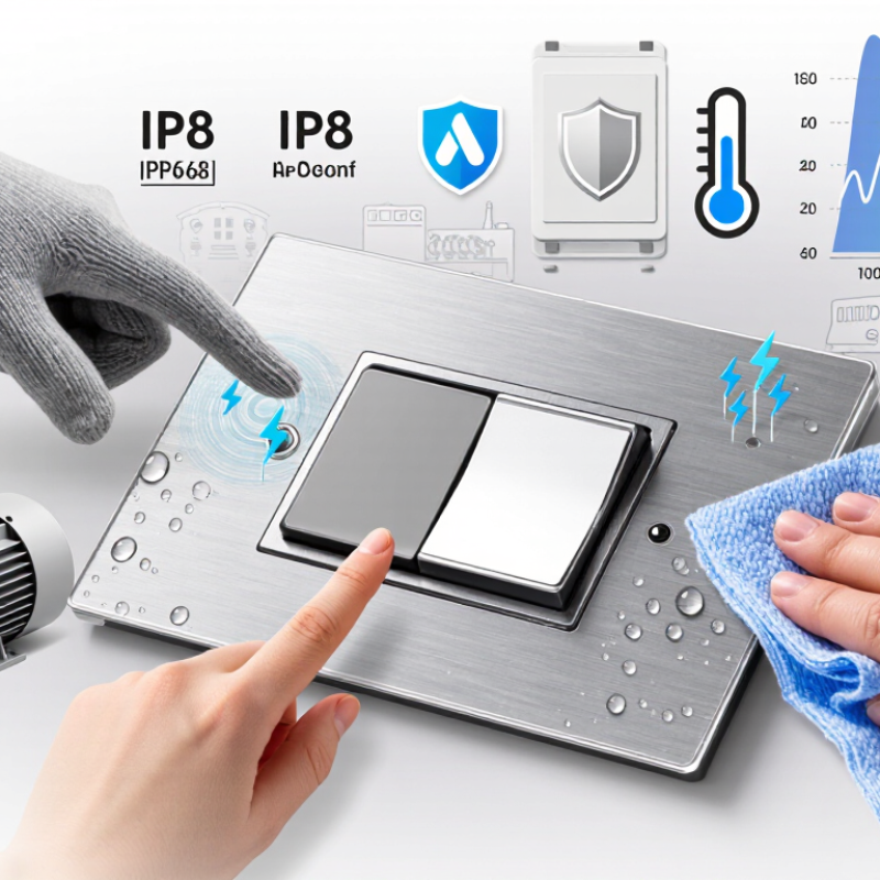
A capacitive switch is an electronic control that detects changes in electrical capacitance. Unlike a mechanical button, it has no moving contact that physically clicks or slides. A conductive electrode sits behind glass, plastic, or another insulating surface. When a finger approaches, the body changes the local electric field. The circuit measures that change and interprets it as an input.
The surface may look simple. The engineering is less obvious. During practical testing, I check response distance, activation consistency, and recovery after repeated touches. A dry fingertip usually produces a clear signal. Water, heavy gloves, dust, and nearby metal can alter the result. That assumption can fail.
Choosing the right capacitive switch means matching the sensor to its working environment. A kitchen control may need moisture-resistant sensing and a surface that wipes clean. An industrial panel may require stronger noise filtering and reliable operation through thicker protective material. For outdoor equipment, temperature changes deserve attention. Small design details matter, including electrode size, illumination, mounting space, and controller sensitivity.
I once treated a thick cover as a minor detail. It reduced the sensing range more than expected. Testing should happen with the final housing, not only on an open circuit board. Users also vary in touch pressure, skin moisture, and glove material. A switch that feels perfect in a quiet laboratory may respond poorly beside motors or power cables. The best choice comes from measured conditions, though real-world behavior can still surprise you.
How to Choose the Right Capacitive Switch?
How Capacitive Switches Work
A capacitive switch detects a small change in an electrical field. It does not need a mechanical button to move. Behind the front panel, a conductive electrode holds a tiny electrical charge. When a finger approaches, the body changes the electrode’s capacitance. A controller measures that change and compares it with a programmed threshold. If the signal is strong enough, the switch activates.
The sensing surface may be glass, plastic, or another thin nonconductive layer. Its thickness matters. Thick panels can weaken the signal, while moisture may create false touches. Grounding, electrode size, and nearby metal also affect performance. In practical testing, a switch can work perfectly on a dry bench but respond poorly inside a finished enclosure. That lesson is easy to overlook. Gloves, wet fingers, and electrical noise may also reduce reliability. Some assumptions fail.
Tips: Test the complete assembly, not only the sensor. Try dry and wet surfaces. Check bare fingers and common gloves. Adjust sensitivity carefully. Excessive sensitivity can cause accidental activation. For public equipment, use clear feedback, such as a light or soft tone. Keep the active area large enough for comfortable contact, but separate nearby electrodes to prevent cross-triggering. Record results at different temperatures, because materials and human touch can behave differently.
Choosing a capacitive switch starts with measurable specifications, not appearance. In practical panel testing, compare sensing distance, response time, and target compatibility. A switch that detects a finger at five millimeters may react differently to a wet glove. Check performance with bare fingers, work gloves, and protective covers. Small differences matter. Ask for test conditions, not only headline figures.
Electrical specifications affect reliable integration. Verify operating voltage, standby current, maximum switching current, and output type. Some controls need a momentary signal, while others require latching behavior. Confirm compatibility with the controller before installation. Review the IP rating, operating temperature, humidity range, and resistance to cleaning chemicals. IP ratings describe tested protection levels, so request supporting test details when the environment is demanding.
Physical details are easy to overlook. Measure panel thickness, cutout size, mounting depth, and indicator visibility from the operator’s normal position. Tactile, visual, or audible feedback can reduce accidental activation, especially near machinery. Electromagnetic interference testing also deserves attention in crowded control cabinets. My early comparisons focused too heavily on response time. That was a mistake. Long-term reliability depended more on sealing, wiring, and stable detection. Leave room for installation tolerances, because real panels are rarely perfect.
Selecting a capacitive switch starts with the user’s environment, not its appearance. A kitchen panel may face steam, splashes, and greasy fingers. A medical device may need a smooth surface, clear feedback, and simple cleaning. For outdoor equipment, temperature changes and moisture deserve serious attention. Consider the overlay material, activation distance, response time, and required sensitivity. If users wear gloves, test the switch with those gloves. Bare-finger testing can create false confidence.
Tips:
The controller and switch should work as one system. Review signal requirements, wiring distance, electromagnetic noise, and available power. A switch that feels excellent in a quiet laboratory may behave poorly beside motors or wireless circuits. Add visual or audible feedback when users need confirmation. Avoid choosing the most sensitive option automatically; excessive sensitivity can cause accidental activation. I have seen prototypes fail because the enclosure changed the sensing field. Small mechanical details matter. Build a sample unit early, then test temperature, moisture, repeated touches, and cleaning routines. No checklist replaces practical testing.
How to Choose the Right Capacitive Switch?
Installation and performance depend on more than the switch’s rated sensitivity. The panel material, grounding path, and installation environment can change touch response. During field testing, I place the switch behind the final overlay, not bare on the workbench. Glass, acrylic, and coated plastics produce different signal levels. A 1–3 mm overlay often works well, but the manufacturer’s sensing range must be verified under real conditions.
Moisture deserves serious attention. A wet finger, cleaning spray, or condensation can create false activations. Select a sealed construction when the enclosure faces kitchens, medical rooms, or outdoor air. Check the stated ingress rating under IEC 60529, then test it after cable entry and assembly. Laboratory results may look excellent. Production units can behave differently.
Electrical noise is another practical concern. Route sensing cables away from motors, relays, and switching power supplies. Confirm immunity using IEC 61000-4-2 methods, including 8 kV contact and 15 kV air-discharge tests where applicable. The 2024 Global E-waste Monitor recorded 62 million tonnes of electronic waste in 2022. A durable, serviceable switch can support longer equipment life, although this benefit depends on the whole product design. I have also seen over-sensitive controls fail user trials. More sensitivity is not always better. Test with gloves, wet hands, temperature changes, and repeated cleaning before approving the design.
Installation and performance should be evaluated together. The chart compares representative engineering reference values for three common capacitive switch installation approaches. Actual limits should be confirmed against the selected component’s datasheet and the target application.
Panel thickness indicates the typical mounting material range, sensing distance represents the nominal activation gap, and temperature span shows the approximate operating range width. Sealed panel designs generally require more installation effort but provide greater protection for outdoor, wet, or frequently cleaned equipment.
„Thanks to the LUVIR technology, the solder resist process could be switched directly from the previously used mask exposure to direct exposure. As an outstanding digital solution on the market, this technology has been able to demonstrate fast process times and superior quality on our certified conventional ink in production. This allowed us to fully digitize the solder mask process at low cost – without process or ink adjustments. An excellent benefit to our production in Rot am See.“
Ralf Göhringer (Head of Production WE Rot am See)
I would definitely recommend the Limata machine and team for a future company purchase
Michael Greenaway
Compunetics Inc.
“The Limata ldi has been amazing!! Best thing we did was buy this machine”
Richard Brady
GM
Circuitlabs
“Since 2019, we have been running the Limata X1000 LDI system (including LUVIR for solder mask imaging) in daily production as an addition to our current process with film. The machine was capable of properly exposing Taiyo PSR-4000 BN (DI) solder mask types on normal to high-copper boards using a new and unique direct imaging process. The machine operating interface is very user friendly which allowed for a quick technical training curve. The pre-registration processing reduced several seconds of production time at every print. Limata support and service staff is incomparable. They supported our team every step of the way at basically any time of the day or night, with literally, an immediate response time, customizing the software interface to best fit our Operations and needs.
We have exposed more than 8,000 prints since end of October, on various solder mask colors and some resist film panels. Limata, has proven to be very capable and innovative. They are a strong contender in the industry.
We have very much enjoyed this project, and working with the team!
Thank you Limata for the continued support and being a part of our growth.”
Bill Sezate
Vice President, GM
Summit Interconnect
As a replacement to our current contact exposure process with film, the LIMATA X2000 system including LUVIR-Technology was capable of properly exposing non-LDI solder mask types using a direct imaging process. The machine offers cutting edge software with a very intuitive operating interface which allowed for quick technician training curve. The dual drawer system combined with pre-registration processing reduced several seconds of production time at every machine cycle. Limata support and service staff is world class. They added software patches to keep production running at shortest possible response times, customized the software interface to best fit our in-house Operations system, and even wrote a step-by-step machine processing manual. As a result of the project, we have exposed more than 16,000 times on various product types and solder mask brands/colors. Limata, in a very short timeframe as a company, has definitely shown they are truly innovative and will be challenging the industry of direct imaging for the top spot.
Kevin Beattie
Process Engineer
TTM Technologies
Forest Grove Division