Threaded Inserts can turn a thin wall, plastic housing, or soft aluminum part into a repeatable threaded joint. Choosing one is not just a matter of matching a screw. The insert must suit the base material, expected load, installation method, temperature, and service environment. Grand View Research estimated the global fasteners market at USD 90.6 billion in 2023, with projected growth through 2030. That broad market figure signals the scale of fastening applications; it does not prove which insert will work in a particular design. The details matter.
A practical selection starts with the substrate and the job the joint must perform. For example, an insert in a molded nylon panel may need different geometry and installation control than one fitted into a tapped metal plate. Compare thread size, insert length, pull-out resistance, torque-out resistance, and the manufacturer’s recommended hole dimensions. Check installation guidance from suppliers such as SPIROL and PennEngineering, then verify ratings against the exact material and process. Catalog values depend on test conditions. Not always. A datasheet cannot fully predict a rough production hole, variable wall thickness, or repeated assembly in the field. This guide explains how to narrow the options, read performance data carefully, and test a representative joint before committing to production. A small prototype can reveal a poor fit early. It may not capture every service condition, though, so document the limits and reassess when materials or loads change.
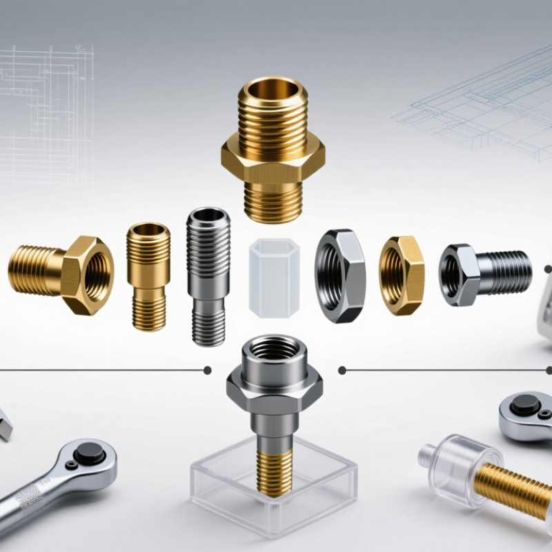
A threaded insert must match the load path, not just the screw size. Estimate tensile, shear, and repeated loads, then check the insert maker’s pull-out data for your exact base material and installation method. ASTM B209 sets a 290 MPa minimum tensile strength for 6061-T6 sheet. That figure describes the sheet, not an insert’s pull-out capacity. Thin walls, edge distance, and hole quality can sharply change performance. Small details matter.
Base material and service conditions deserve equal attention. Soft aluminum, brittle plastics, and composites need different engagement lengths and installation controls. NASA’s Fastener Design Manual, RP-1228, explains that friction makes torque an imperfect guide to clamp load. So, do not treat a tightening value as proof of joint strength. Check temperature, moisture, vibration, corrosion exposure, and how often the joint will be opened. For a vibrating assembly, verify locking performance under representative testing; a static pull test alone may miss loosening. I would also document the hole size and installation torque, though those records are easy to neglect on a busy shop floor. If published data do not match your material thickness or load direction, test a representative sample before production.
Representative specified minimum tensile strength of common metal base materials
Values are approximate specified minimums for the listed material specifications: ASTM A36 steel, ASTM B209 6061-T6 aluminum, and ASTM A240 304 stainless steel. Base-material tensile strength is not the insert’s pull-out capacity. Choose an insert using the actual load direction and magnitude, material thickness, engagement, installation method, and service conditions; use application-specific design data or testing for final verification.
The right insert depends on the substrate and the space available for installation. A helical insert suits a tapped metal hole when the surrounding material can support the larger prepared opening. Its coil spreads thread contact across the hole, which can help when softer metal needs repeated screw removal. Installation needs room for a drill, tap, and driving tool. Access matters.
A solid insert is worth considering for higher loads or frequent assembly, provided the part has enough wall thickness. Its body takes up more space, and some designs need a shoulder, key, or larger external thread to prevent rotation. Check the distance to nearby edges before drilling; a strong insert can still split a thin section. Not always obvious.
Press-in inserts are commonly used in plastics and other softer substrates. Their knurls or barbs grip the surrounding material, but performance depends on the material, hole size, and installation force. Too much force may crack a brittle plastic; too little may let the insert turn under torque. For thermoplastics, heat-assisted installation may reduce stress, though temperature and alignment need control. A useful selection check is to test the actual substrate and fastener together. I would not rely on a material label alone. Just a small trial hole can reveal problems a drawing misses.
| Insert type | Typical substrate | Installation and access | Key advantages | Limitations and checks | Good choice when… |
|---|---|---|---|---|---|
| Helical wire insert | Metals with adequate wall thickness, including aluminum, magnesium, and steel. A compatible insert and installation process are required for the selected material. | Usually requires drilling or sizing the hole, tapping it with the specified STI tap, and installing the wire with a tool. Generally installed from one side with straight access to the hole; some designs require tang removal. | Provides a wear-resistant internal thread and can repair certain damaged or stripped tapped holes. Its thin-wall form can preserve more surrounding material than many solid inserts. | Requires the correct STI tooling and controlled installation. It is not a direct press-fit solution, and the parent material must support the tapped insert cavity. Confirm engagement length, edge distance, and load requirements. | The part is metal, space around the fastener is limited, and a durable internal thread or repair is needed. |
| Solid insert | Metals, plastics, or composites, depending on insert design, retention method, and the substrate’s strength and temperature limits. | Commonly installed into a prepared hole. Designs may use external threads, keys, knurls, or other locking features. Installation typically needs axial access and room for the specified drill, tap, driver, or pressing tool. | Offers a rigid, substantial threaded body. Some designs provide mechanical locking against rotation or pull-out when installed correctly. Can suit applications that need a robust, replaceable threaded interface. | Often needs a larger hole and more surrounding material than a wire insert. Installation may remove more substrate and can be difficult in confined areas. Performance depends strongly on insert geometry and the host material. | A rigid insert body or a specific mechanical locking feature is required, and there is enough material and access for its installation method. |
| Press-in insert | Most commonly used in thermoplastics and other materials specifically suited to interference-fit installation. Some press-fit designs are made for metal; verify the insert and substrate specifications. | Pressed into a prepared hole using a controlled press or installation tool. Usually needs access from the insertion side and support beneath or around the part to avoid distortion or cracking. | Can provide a threaded attachment point without cutting an internal thread in the part. Installation can be straightforward in production when hole size, alignment, and pressing conditions are controlled. | Retention depends on hole dimensions, material properties, wall thickness, and installation conditions. Excessive interference or poor support can damage the substrate. Not interchangeable with inserts intended for heat or ultrasonic installation. | The substrate is designed for a press fit, the hole can be made to specification, and a press or suitable installation tool can reach the insertion side. |
Selection note: Confirm the insert manufacturer’s specifications for substrate compatibility, hole preparation, minimum wall thickness, installation method, temperature range, and allowable loads. Actual performance depends on the complete joint design and installation quality.
For an M6 × 1.0 thread, M6 indicates a nominal 6 mm diameter, while 1.0 mm is the distance between thread peaks. Match this specification to the screw that will enter the insert. A different pitch may feel close at first, then bind or damage the threads. Check the drawing or product data rather than relying on a screw that “seems to fit.”
Thread size is only part of the decision. The insert’s outer dimensions, installation method, and required hole preparation depend on its design and the material around it. A press-in insert for plastic, for example, may need a different hole than a solid insert installed in metal. Tolerance and engagement length matter, too. A chart helps, but it can create false confidence if the parent material or application is overlooked.
Tips: Confirm the M6 × 1.0 pitch with a thread gauge, then test the screw by hand. It should turn smoothly, without force. Follow the insert maker’s specified hole size and installation steps; do not assume every M6 insert uses the same preparation. Check a sample assembly before repeating the process. A small test can reveal a poor fit early.
A reliable insert selection begins with the drawing and the applicable edition of ASME B18.29.1. The standard provides dimensional requirements for helical coil screw thread inserts, including free-running and screw-locking types. Match the insert’s nominal thread size and specified length to the drawing; do not rely on a catalog description alone. Small differences matter. A length that looks suitable on a screen may leave too little engagement in a thin section or interfere with a nearby feature.
Check the required STI tapped-hole dimensions alongside the insert dimensions. The insert and its prepared hole are a system: a correct insert can still fit poorly if the tap size, pitch, or installation depth is wrong. Compare the drawing’s callouts with the standard’s tables, and confirm that the selected type matches the intended assembly. Also check the standard revision referenced by the project. Standards can change, and a familiar part number is not proof of compliance. When a callout is unclear, pause and verify it with the design authority or a qualified engineering reference. That extra check may feel fussy. It is usually cheaper than discovering a proud coil or damaged threads during assembly.
How to Choose the Right Threaded Inserts?
Verify Pull-Out, Torque, and Temperature Ratings with Test Data
A rating only helps when its test conditions match your assembly. Check the insert material, host material, hole size, and installation method in the test report. A pull-out result from a thick steel plate may not predict performance in thin aluminum or plastic. Look for the specimen dimensions, sample count, and failure mode—not just the highest number. Small details matter.
Torque needs the same scrutiny. Confirm whether the reported value measures installation torque, thread-stripping resistance, or insert rotation under load. These are different limits. Compare test results with your fastener size and expected service loads, then leave a practical margin. Temperature data should cover both continuous exposure and short heat spikes. Ask whether testing included repeated heating and cooling, since that can change fit or holding strength.
Tips: Request the actual test method and results, not only a catalog rating. Check that the tested insert and substrate match your parts. If they do not, run a small trial using your own hole dimensions and installation tool. It may feel slower, but a representative test can reveal a weak fit before production. One test will not answer everything.
„Thanks to the LUVIR technology, the solder resist process could be switched directly from the previously used mask exposure to direct exposure. As an outstanding digital solution on the market, this technology has been able to demonstrate fast process times and superior quality on our certified conventional ink in production. This allowed us to fully digitize the solder mask process at low cost – without process or ink adjustments. An excellent benefit to our production in Rot am See.“
Ralf Göhringer (Head of Production WE Rot am See)
I would definitely recommend the Limata machine and team for a future company purchase
Michael Greenaway
Compunetics Inc.
“The Limata ldi has been amazing!! Best thing we did was buy this machine”
Richard Brady
GM
Circuitlabs
“Since 2019, we have been running the Limata X1000 LDI system (including LUVIR for solder mask imaging) in daily production as an addition to our current process with film. The machine was capable of properly exposing Taiyo PSR-4000 BN (DI) solder mask types on normal to high-copper boards using a new and unique direct imaging process. The machine operating interface is very user friendly which allowed for a quick technical training curve. The pre-registration processing reduced several seconds of production time at every print. Limata support and service staff is incomparable. They supported our team every step of the way at basically any time of the day or night, with literally, an immediate response time, customizing the software interface to best fit our Operations and needs.
We have exposed more than 8,000 prints since end of October, on various solder mask colors and some resist film panels. Limata, has proven to be very capable and innovative. They are a strong contender in the industry.
We have very much enjoyed this project, and working with the team!
Thank you Limata for the continued support and being a part of our growth.”
Bill Sezate
Vice President, GM
Summit Interconnect
As a replacement to our current contact exposure process with film, the LIMATA X2000 system including LUVIR-Technology was capable of properly exposing non-LDI solder mask types using a direct imaging process. The machine offers cutting edge software with a very intuitive operating interface which allowed for quick technician training curve. The dual drawer system combined with pre-registration processing reduced several seconds of production time at every machine cycle. Limata support and service staff is world class. They added software patches to keep production running at shortest possible response times, customized the software interface to best fit our in-house Operations system, and even wrote a step-by-step machine processing manual. As a result of the project, we have exposed more than 16,000 times on various product types and solder mask brands/colors. Limata, in a very short timeframe as a company, has definitely shown they are truly innovative and will be challenging the industry of direct imaging for the top spot.
Kevin Beattie
Process Engineer
TTM Technologies
Forest Grove Division
