In the world of electronics, reliability is key. One vital component that helps ensure this reliability is the Signal Choke. This component plays a crucial role in filtering noise. By doing so, it enhances the performance of electronic devices. Any project can greatly benefit from incorporating a Signal Choke.
Implementing a Signal Choke can improve the overall efficiency of circuits. It allows signals to pass through while blocking unwanted interference. Many engineers recognize its importance, but not all understand its full potential. There may be mistakes in the selection process, leading to suboptimal performance.
Even experienced designers must pause and reflect on their choices. Understanding how a Signal Choke works involves considering specifics. The right choke can make a significant difference in project outcomes. By ensuring proper application, one can elevate their electronics projects to new heights.
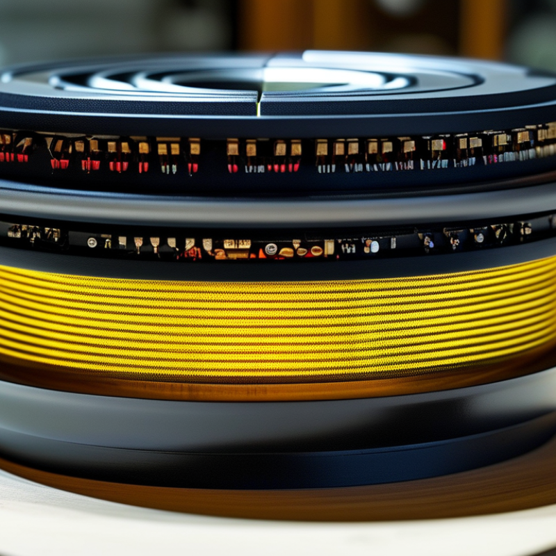
Signal chokes are crucial components in electronics projects. They help manage and reduce electromagnetic interference (EMI). This interference can disrupt the functionality of your devices. By filtering unwanted high-frequency noise, signal chokes improve signal integrity. This aspect is vital in ensuring precise performance.
Understanding their construction can provide deeper insights. Signal chokes often consist of coils wrapped around magnetic cores. These designs allow them to store energy in magnetic fields. When selecting one, pay attention to impedance and frequency ratings. Misjudging these factors could lead to ineffective results. Sometimes, developers overlook the choke's role, focusing solely on other parts like resistors and capacitors. This lack of recognition can lead to projects falling short of technical expectations.
Incorporating signal chokes into your designs can bring notable advantages. They enhance overall circuit stability and reduce power loss. However, achieving the right implementation involves understanding your project’s unique needs. It’s necessary to reflect on past projects to identify areas of improvement. By refining your approach to selecting and integrating signal chokes, you can elevate the quality of your electronics work.
Signal integrity plays a crucial role in electronics projects. It ensures that the signals transmitted through your circuits remain clear and uncorrupted. When signal integrity is compromised, projects can experience issues like noise, distortion, or even failure. Consequently, understanding how to maintain signal integrity is essential for anyone involved in electronics.
Chokes are vital components in preserving this integrity. They filter out unwanted high-frequency noise that can interfere with your signals. Without proper filtering, your electronics may not function as intended. The right choke can significantly improve performance while reducing errors. Choosing the wrong choke could lead to chaotic signal behavior. Small adjustments can sometimes lead to big changes.
Many hobbyists overlook the nuances of signal integrity. They often focus on bigger components and overlook the importance of small details. Investing time in understanding these aspects can make a difference. Testing prototypes thoroughly helps identify weaknesses. Ignoring these elements can result in frustrating setbacks. Signal integrity deserves attention in every project for delivering reliable outcomes.
Electromagnetic interference (EMI) is a common issue in electronics projects. It can disrupt signals and degrade performance. Understanding how to mitigate EMI is crucial for any electronics engineer. This is where signal chokes come into play. They are essential components designed to filter out unwanted frequencies. By using a signal choke, you can improve the reliability of your circuit.
Signal chokes act as a barrier against noise in electrical signals. They allow the desired signal to pass while blocking harmful interference. This selective filtering can enhance the clarity and stability of your project. For example, in audio applications, a signal choke can minimize buzzing and static, leading to improved sound quality. However, if not properly integrated, a choke can introduce its own set of issues. It is vital to ensure the choke's specifications match the project requirements to avoid signal distortion.
Choosing the right choke requires careful consideration. Factors such as inductance, resistance, and frequency response can drastically affect performance. A mistake in selection can lead to more problems than solutions. Always test your setup thoroughly to identify any unexpected behaviors. Continuous learning from these experiences will help refine your skills and improve future projects.
When selecting a signal choke for electronics projects, matching the component to project needs is critical. Signal chokes control electromagnetic interference (EMI) and enhance circuit performance. Recent industry data indicates that incorporating a quality signal choke can reduce EMI by up to 35%. This improvement is essential for sensitive applications, such as communication devices or medical equipment.
Choosing the right signal choke depends on several factors. Consider the choke’s impedance, operating frequency, and current rating. For instance, a choke with higher inductance is beneficial for low-frequency applications, while lower inductance suits high-frequency scenarios. It’s equally important to evaluate heat dissipation. An inefficient choke may overheat, leading to failures and unreliable performance.
Tip: Always test your chosen choke in the actual circuit before finalizing. This allows you to measure real-world performance. It’s also wise to have a few spare options at hand during prototyping. This way, you can adjust based on actual needs.
The wrong selection can lead to unexpected issues. While your project may function initially, unforeseen problems may arise later. Maintaining a balance between cost and quality is essential when choosing components. Avoiding shortcuts can lead to long-term success.
| Parameter | Description | Value |
|---|---|---|
| Inductance | The ability to store electrical energy in a magnetic field | 10 µH - 2200 µH |
| Current Rating | Maximum current the choke can handle without saturation | 1 A - 10 A |
| DC Resistance | Resistance to direct current, affecting efficiency | 0.1 Ω - 5 Ω |
| Self-Resonant Frequency | Frequency at which the choke can no longer store energy | 100 MHz - 1 GHz |
| Size | Physical dimensions which affect placement in designs | 0402 to 2512 |
| Temperature Range | Operating temperature limits for reliable performance | -40°C to +125°C |
In circuit design, signal chokes play a vital role. They filter out unwanted high-frequency noise. This ensures signals remain clean and reliable. Designers often use them in power supply units and audio devices. When a circuit experiences noise, it can lead to failures. Signal chokes prevent this by smoothing out the signals.
Another common application is in telecommunications. Signal chokes help maintain signal integrity over long distances. Poor signals can disrupt communication or cause data loss. With the right choke, designers can enhance performance significantly.
Industrial electronics also benefit from signal chokes. They protect sensitive components from voltage surges and electromagnetic interference.
However, users must consider choke selection carefully.
Not every choke suits every project. Factors like frequency range and inductance matter. Testing is crucial, as unexpected performance issues may arise. Selecting the wrong choke can lead to system inefficiencies. Hence, careful planning and testing are essential.
„Thanks to the LUVIR technology, the solder resist process could be switched directly from the previously used mask exposure to direct exposure. As an outstanding digital solution on the market, this technology has been able to demonstrate fast process times and superior quality on our certified conventional ink in production. This allowed us to fully digitize the solder mask process at low cost – without process or ink adjustments. An excellent benefit to our production in Rot am See.“
Ralf Göhringer (Head of Production WE Rot am See)
I would definitely recommend the Limata machine and team for a future company purchase
Michael Greenaway
Compunetics Inc.
“The Limata ldi has been amazing!! Best thing we did was buy this machine”
Richard Brady
GM
Circuitlabs
“Since 2019, we have been running the Limata X1000 LDI system (including LUVIR for solder mask imaging) in daily production as an addition to our current process with film. The machine was capable of properly exposing Taiyo PSR-4000 BN (DI) solder mask types on normal to high-copper boards using a new and unique direct imaging process. The machine operating interface is very user friendly which allowed for a quick technical training curve. The pre-registration processing reduced several seconds of production time at every print. Limata support and service staff is incomparable. They supported our team every step of the way at basically any time of the day or night, with literally, an immediate response time, customizing the software interface to best fit our Operations and needs.
We have exposed more than 8,000 prints since end of October, on various solder mask colors and some resist film panels. Limata, has proven to be very capable and innovative. They are a strong contender in the industry.
We have very much enjoyed this project, and working with the team!
Thank you Limata for the continued support and being a part of our growth.”
Bill Sezate
Vice President, GM
Summit Interconnect
As a replacement to our current contact exposure process with film, the LIMATA X2000 system including LUVIR-Technology was capable of properly exposing non-LDI solder mask types using a direct imaging process. The machine offers cutting edge software with a very intuitive operating interface which allowed for quick technician training curve. The dual drawer system combined with pre-registration processing reduced several seconds of production time at every machine cycle. Limata support and service staff is world class. They added software patches to keep production running at shortest possible response times, customized the software interface to best fit our in-house Operations system, and even wrote a step-by-step machine processing manual. As a result of the project, we have exposed more than 16,000 times on various product types and solder mask brands/colors. Limata, in a very short timeframe as a company, has definitely shown they are truly innovative and will be challenging the industry of direct imaging for the top spot.
Kevin Beattie
Process Engineer
TTM Technologies
Forest Grove Division