Industrial Vacuum Piping can look straightforward on a drawing: a pump, a header, and several branches. On a factory floor, the details matter. Pipe diameter, route length, fittings, and leak-tight joints all affect airflow and pressure at the point of use. A narrow branch may leave a remote machine struggling while the pump runs harder. Buyers should compare complete system designs, not just pipe material or quoted price.
Engineering professor and author Henry Petroski wrote, “Science is about knowing; engineering is about doing.” That idea suits vacuum-piping purchases. Buyers need specifications, but they also need evidence that a proposed layout fits their process. Ask suppliers to explain pressure-drop assumptions, connection details, support spacing, and how the design handles future equipment. Look for relevant project experience and clear commissioning records. Small details count.
This guide compares leading Industrial Vacuum Piping system options through practical buyer questions: material, installation, maintenance, scalability, and total operating cost. Stainless steel, aluminum, and engineered polymer systems each have trade-offs. No option wins everywhere. Dust, temperature, cleaning routines, and plant layout change the answer. A neat catalog diagram cannot capture every site condition. That is worth remembering. Verify the design against real operating requirements, and ask what happens when demand changes. Even careful buyers can miss a constraint; a second review by a qualified vacuum-system professional can expose it before installation.
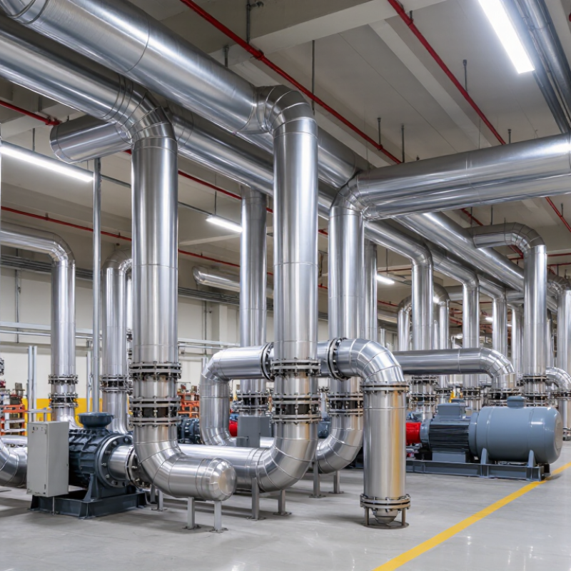
Industrial vacuum piping systems connect workstations, pickup hoods, and tools to a central vacuum source. They carry air and process debris through a sealed network under negative pressure. A separator or filter removes collected material before air reaches the vacuum unit. Pipe diameter, bends, and branch locations affect airflow, so a system needs to match the material and operating demand.
During operation, suction draws air through each pickup point and along the pipe. The vacuum unit maintains airflow, while filters capture fine particles that the separator does not remove. Smooth interiors and gradual bends can help reduce resistance. Leaks matter: even a small gap near a joint may weaken suction at a distant workstation. A layout can look tidy on paper and still clog if its velocity or branches are poorly matched. That deserves a second look.
Tips: Check joints for leaks and inspect filters on a regular schedule. Note changes in suction and unusual buildup, especially near bends. Keep grounded, conductive components where the collected material requires them. Do not assume one pipe size suits every pickup point; actual performance depends on distance, debris, and simultaneous use.
Industrial vacuum piping is more than a run of tubes; each joint and fitting affects system performance. Straight pipe carries flow, while elbows, tees, and reducers shape its route. Keep bends gentle where possible, since abrupt changes can add resistance and complicate cleaning. Small details matter. Flanges and clamps allow sections to be inspected or replaced, but their seals must suit the vacuum level and process conditions. Metal gaskets can work in demanding applications, while elastomer seals are easier to install and may be suitable for less stringent service. Check temperature and chemical compatibility before selecting either.
Stainless steel is often chosen for its corrosion resistance and cleanable surface. Aluminum is lighter and can be practical in some systems, while carbon steel may suit less corrosive duties if its internal condition is controlled. Material choice should also consider outgassing, contamination risk, and the pumped process—not just purchase cost. Add isolation valves, vacuum-rated gauges, and supports that prevent pipe weight from stressing connections. A sight glass can help operators observe a process, but it introduces another sealed joint to maintain. In real installations, the neatest drawing does not always produce the easiest maintenance; access for a wrench is easy to overlook. Test joints for leaks after assembly, and record the materials and seals used.
Industrial vacuum piping commonly uses a central header, a ring main, or dedicated point-of-use lines. A central system connects several machines to pumps in one location. It works well when demand is steady and equipment is clustered. Long branches, however, can reduce vacuum at distant pickup points. A ring main supplies branches from two directions, which can help balance flow. Dedicated lines isolate equipment with unusual or fluctuating demand. More pipe, though.
Material and layout both matter. Stainless steel resists corrosion and suits clean processes; steel can handle demanding industrial environments. Aluminum systems are lighter and easier to modify. Flexible hose is useful at moving tools, but long or sharply bent runs can restrict flow. Keep rigid pipe routes short, limit elbows, and place vacuum gauges near remote machines. A gauge beside the pump may not reveal losses at the far end.
The U.S. Department of Energy’s Improving Compressed Air System Performance sourcebook reports that leaks can waste 20–30% of compressor output in many compressed-air systems. That figure is not a vacuum-piping failure rate, but it highlights the value of leak checks and maintenance. Check joints, filters, and isolation valves under operating conditions. One detail is easy to miss: actual demand changes. Measure at the furthest pickup before choosing pipe diameter; calculations alone can feel reassuring, yet still miss a poor connection.
| System Type | Typical Materials | Common Applications | Key Advantages | Buyer Considerations | Relative Cost |
|---|---|---|---|---|---|
| Carbon Steel Piping | Welded or threaded carbon steel pipe and fittings | Centralized plant vacuum networks, general manufacturing, and industrial dust collection | Strong, widely available, and suitable for durable fixed installations | Assess corrosion exposure, internal cleanliness, joint quality, and support requirements. Coatings may be needed in corrosive environments. | Moderate |
| Stainless Steel Piping | Stainless steel pipe, tubing, and compatible fittings | Food and beverage processing, pharmaceutical production, clean areas, and corrosive environments | Good corrosion resistance and cleanability; appropriate grades can support stringent hygiene requirements | Specify the stainless steel grade, surface finish, joining method, and cleaning requirements for the process. | High |
| Aluminum Modular Piping | Extruded aluminum pipe with modular connectors and fittings | Factory vacuum distribution, production cells, and systems that may need reconfiguration | Lightweight, modular, and relatively quick to install or modify | Confirm vacuum-pressure rating, connector compatibility, temperature limits, and suitability for the conveyed material. | Moderate to high |
| Galvanized Steel Piping | Zinc-coated steel pipe and fittings | General-purpose plant installations where a coated steel pipe is appropriate | Rigid construction with a protective zinc coating for many ordinary service conditions | Check coating compatibility with the process and environment. Avoid assuming it is suitable for high-purity or strongly corrosive service. | Low to moderate |
| Flexible Vacuum Hose Connections | Application-specific flexible hose, often with reinforced construction | Equipment connections, moving machinery, vibration isolation, and short drops from rigid headers | Accommodates movement and helps simplify connections where rigid pipe is impractical | Use hose rated for the required vacuum, temperature, abrasion, and chemical exposure. Long or undersized runs can increase pressure loss. | Low to moderate |
Selection note: Choose piping based on the required vacuum level, flow rate, pipe diameter and length, conveyed material, temperature, corrosion exposure, cleanliness requirements, and applicable codes. Confirm that the complete piping system and its joints are rated for the intended service.
Selecting an industrial vacuum piping system starts with the process, not a product photo. Map every pickup point, pipe length, bend, and elevation change. Fine powder, metal chips, and damp debris behave differently in a line. Estimate the load during peak production, not just a quiet shift. Small mismatches matter.
Check particle size, moisture, temperature, and abrasiveness before choosing pipe material and diameter. These factors affect wear, blockage risk, and airflow. Ask for pressure-drop calculations across the full layout, including branches that may operate together. A system that looks adequate on paper can lose performance when several operators use it at once. That detail is easy to overlook.
Plan for maintenance, too. Long, inaccessible runs make inspections and blockage clearing harder. Include cleanout points where buildup is likely, and confirm that joints can handle the expected vacuum and material impact. Request test data or a commissioning plan, then compare measured airflow with the design target. Site conditions often differ from drawings; even a careful estimate can miss a troublesome bend or changing production load. Keep room for adjustment where practical.
Industrial vacuum piping performs reliably when its layout matches the material, airflow, and duty cycle. Before installation, confirm pipe diameter, wall thickness, and temperature limits against the system design. Keep runs short and bends gradual; tight elbows can collect dust and increase pressure loss. Support long spans so joints do not carry the pipe’s weight. Leave access near cleanouts and isolation points. Small details matter.
During installation, remove burrs and debris, then check joints for leaks before connecting production equipment. A suitable leak-check method can reveal poor seals. Follow procedures appropriate to the site and material. Inspect hangers and flexible connections, and verify grounding or bonding provisions where required by the design. After startup, record baseline vacuum, airflow, and motor load. These readings help reveal changes over time. Not every layout is perfect; a crowded retrofit may deserve another review.
Tips: Check cleanouts regularly, especially after handling fine or damp material. Look for wear at elbows, reducers, and pickup branches. Listen for new whistling and compare readings with the baseline. Replace damaged seals, but investigate why they failed. A quick patch can hide a recurring alignment problem. Keep inspection notes brief and dated.
„Thanks to the LUVIR technology, the solder resist process could be switched directly from the previously used mask exposure to direct exposure. As an outstanding digital solution on the market, this technology has been able to demonstrate fast process times and superior quality on our certified conventional ink in production. This allowed us to fully digitize the solder mask process at low cost – without process or ink adjustments. An excellent benefit to our production in Rot am See.“
Ralf Göhringer (Head of Production WE Rot am See)
I would definitely recommend the Limata machine and team for a future company purchase
Michael Greenaway
Compunetics Inc.
“The Limata ldi has been amazing!! Best thing we did was buy this machine”
Richard Brady
GM
Circuitlabs
“Since 2019, we have been running the Limata X1000 LDI system (including LUVIR for solder mask imaging) in daily production as an addition to our current process with film. The machine was capable of properly exposing Taiyo PSR-4000 BN (DI) solder mask types on normal to high-copper boards using a new and unique direct imaging process. The machine operating interface is very user friendly which allowed for a quick technical training curve. The pre-registration processing reduced several seconds of production time at every print. Limata support and service staff is incomparable. They supported our team every step of the way at basically any time of the day or night, with literally, an immediate response time, customizing the software interface to best fit our Operations and needs.
We have exposed more than 8,000 prints since end of October, on various solder mask colors and some resist film panels. Limata, has proven to be very capable and innovative. They are a strong contender in the industry.
We have very much enjoyed this project, and working with the team!
Thank you Limata for the continued support and being a part of our growth.”
Bill Sezate
Vice President, GM
Summit Interconnect
As a replacement to our current contact exposure process with film, the LIMATA X2000 system including LUVIR-Technology was capable of properly exposing non-LDI solder mask types using a direct imaging process. The machine offers cutting edge software with a very intuitive operating interface which allowed for quick technician training curve. The dual drawer system combined with pre-registration processing reduced several seconds of production time at every machine cycle. Limata support and service staff is world class. They added software patches to keep production running at shortest possible response times, customized the software interface to best fit our in-house Operations system, and even wrote a step-by-step machine processing manual. As a result of the project, we have exposed more than 16,000 times on various product types and solder mask brands/colors. Limata, in a very short timeframe as a company, has definitely shown they are truly innovative and will be challenging the industry of direct imaging for the top spot.
Kevin Beattie
Process Engineer
TTM Technologies
Forest Grove Division