A Millimeter Wave Amplifier boosts signals in the high-frequency bands used by advanced radar, satellite links, and wireless networks. These signals can carry large amounts of data, but they are easily weakened by distance, obstacles, and losses in cables or circuit traces. The amplifier restores signal strength. Small details matter.
Professor Theodore S. Rappaport is a widely cited researcher in millimeter-wave communications. A careful paraphrase of a central idea in his work is: “Millimeter-wave performance depends on the whole link, not just the frequency band.” That perspective helps explain why an amplifier cannot be judged by gain alone. Engineers also examine output power, noise figure, linearity, bandwidth, stability, and heat. A chip may look impressive on a test bench, yet perform differently inside a compact radio with warm components and long signal paths.
This guide introduces how a Millimeter Wave Amplifier works, where it is used, and which specifications deserve close attention. It also considers common amplifier types, including low-noise and Power Amplifiers. Expect trade-offs. More gain can bring more noise, distortion, or heat, depending on the design. The datasheet is a starting point, not the whole story. Real measurements, operating conditions, and careful integration matter. Even experienced teams can miss a layout detail. That is worth remembering.
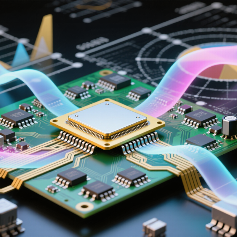
What Is a Millimeter Wave Amplifier?
Definition and Role of a Millimeter Wave Amplifier
A millimeter wave amplifier strengthens radio-frequency signals in frequency ranges commonly associated with roughly 30 to 300 gigahertz. Its role is to provide useful signal gain, either before transmission or after reception. In a transmitter, an amplifier raises signal power so it can feed an antenna. In a receiver, a low-noise amplifier boosts faint incoming signals while adding as little noise as practical. These functions help communication and sensing systems handle weak signals and short wavelengths.
The work is demanding. At millimeter-wave frequencies, small losses in connectors, circuit traces, or packaging can noticeably affect performance. Engineers consider gain, bandwidth, noise, linearity, and heat, then verify results with suitable high-frequency test equipment. A receiver amplifier, for example, may sit close to the antenna to limit losses before the signal reaches it. Placement matters. So does calibration. Lab measurements can differ from real-world results, and that gap is not always easy to explain. An amplifier is not a cure for every link problem; antenna alignment, obstacles, and system design still matter. A useful design balances these factors rather than chasing one impressive specification.
| Dimension | Details | Why It Matters |
|---|---|---|
| Definition | A millimeter wave (mmWave) amplifier is an electronic circuit that increases the power or amplitude of signals at very high radio frequencies. | It helps a weak signal reach the power level needed for transmission, processing, or measurement. |
| Typical frequency range | The term mmWave commonly refers to frequencies from 30 to 300 GHz, corresponding to wavelengths of approximately 10 to 1 millimeter in free space. | Short wavelengths support compact antennas and can enable wide bandwidth, but signals are more sensitive to blockage and propagation loss. |
| Primary role | An amplifier raises signal power while operating over a specified frequency range and within its rated input and output limits. | Amplification can compensate for losses in cables, components, antennas, or a radio link. |
| Common amplifier positions | A power amplifier is commonly placed near a transmitter output; a low-noise amplifier is commonly placed near a receiver input. | Transmitters need sufficient output power, while receivers benefit from boosting weak signals before later stages add more noise. |
| Key performance measures | Typical specifications include operating frequency range, gain (dB), output power (often dBm), noise figure (dB), bandwidth, and linearity. | These measures help determine whether an amplifier fits a system’s coverage, signal-quality, and power requirements. |
| Gain | Gain describes how much an amplifier increases signal power or voltage under specified measurement conditions; it is commonly reported in decibels (dB). | Higher gain is not always better: excessive gain can cause distortion or overload a following circuit. |
| Noise figure | Noise figure indicates how much a component degrades the signal-to-noise ratio. It is especially important for receiver-side amplifiers. | A lower noise figure helps preserve the quality of weak signals, all else being equal. |
| Linearity and saturation | Linearity describes how faithfully an amplifier reproduces signals. At high input levels, an amplifier can approach compression or saturation. | Operating with adequate headroom helps limit distortion, particularly for signals with changing amplitude. |
| Common technologies | Implementations can use semiconductor technologies such as silicon, silicon-germanium, gallium arsenide, or gallium nitride, depending on frequency and performance needs. | Different technologies involve trade-offs in output power, efficiency, integration, cost, and operating frequency. |
| Example application frequencies | Examples include 60 GHz links, 76–81 GHz automotive radar, and systems operating near 94 GHz. | These frequencies are used in applications such as high-capacity communications, radar, imaging, and scientific measurement. |
| Design considerations | Designers account for matching networks, heat dissipation, packaging, interconnect losses, stability, and antenna integration. | At mmWave frequencies, even small physical structures and layout details can significantly affect circuit performance. |
A millimeter-wave amplifier strengthens very high-frequency signals, often in the 24 GHz-and-above range. The FCC’s 2016 Spectrum Frontiers Order covered bands including 28, 37, and 39 GHz. At these frequencies, tiny circuit details matter. A transmitter’s power amplifier boosts the signal before it reaches an antenna; a receiver’s low-noise amplifier raises weak incoming signals while trying to add little noise. Both rely on carefully matched transistor stages, because even short traces can affect signal loss and stability.
Heat is real. Amplifier designers balance gain, noise, efficiency, and temperature, often within a small module near an antenna array. In a beamforming system, several amplifier paths can adjust signal strength and phase, helping steer energy toward a user. The trade-off is that higher output can increase heat and power use.
ITU-R’s IMT-2020 requirements set peak-rate targets of 20 Gbit/s downlink and 10 Gbit/s uplink; these are system targets, not guarantees for an individual amplifier.
That distinction is easy to miss. Bench measurements must therefore check gain, noise figure, output power, and performance across the intended bandwidth. A neat specification sheet may not capture every real-world thermal or layout compromise.
A millimeter-wave amplifier boosts very high-frequency signals, where even short traces can affect performance. Designers commonly arrange several gain stages: a low-power driver feeds a final stage that delivers more output power. A single-stage design can save space, but may not provide enough gain. Heat matters.
Common architectures include cascaded stages, balanced amplifiers, and distributed amplifiers. Cascaded stages build gain step by step, while balanced designs split and recombine signals to improve matching and reduce sensitivity to load changes. Distributed designs use transmission lines and multiple transistor cells to extend bandwidth. Each approach brings trade-offs in size, efficiency, and circuit complexity.
The active devices may use semiconductor processes suited to high frequencies, such as gallium arsenide, gallium nitride, or silicon-germanium. Around them sit input and output matching networks, bias circuits, transmission lines, and a package designed to limit parasitic effects. At these frequencies, a tiny bond wire or imperfect connector can change measured results. Engineers check gain, output power, noise, stability, and temperature across the intended frequency range. Bench measurements can still disagree with simulation; that gap deserves investigation, not a quick excuse.
What Is a Millimeter Wave Amplifier? Performance Characteristics and Design Challenges
A millimeter-wave amplifier boosts radio-frequency signals, commonly across the 24.25–71 GHz range identified for 5G FR2 in 3GPP TS 38.104. Engineers assess gain, bandwidth, noise figure, output power, and linearity together; a strong gain figure alone can hide poor signal quality. At these frequencies, tiny layout changes matter. A few millimeters of transmission line, a connector seam, or a poorly grounded via can affect matching and introduce loss. Thermal management is also demanding: compact amplifier stages must shed heat without compromising the surrounding antenna array.
The propagation environment adds another constraint. ITU-R Recommendation P.676-13 describes strong oxygen absorption near 60 GHz, at roughly 15 dB per kilometer under typical atmospheric conditions. That matters over longer paths, though indoor links are often more affected by antennas, packaging, and feed losses. Designers therefore balance output power against heat, efficiency, and distortion, especially when handling wideband signals with high peak-to-average power ratios. Measurement setup matters, too: cable loss and calibration errors can make a prototype look better—or worse—than it is. Bench results do not always predict performance inside a finished device. That gap deserves more attention.
As frequency increases, free-space path loss also increases for the same distance. These values are calculated for a 1-meter line-of-sight link using the Friis free-space path-loss equation; they exclude additional losses from obstacles, antenna effects, and the atmosphere. Millimeter-wave amplifier designs must account for this link-budget challenge.
A millimeter-wave amplifier raises the power of signals at very high frequencies, helping them travel through communication links or return from distant objects. In 5G networks, that extra gain can support short, high-capacity links between street-level small cells, where buildings and even foliage may weaken signals. The GSMA’s Mobile Economy 2024 report forecasts 5.5 billion 5G connections by 2030. That figure covers all 5G frequency bands, not millimeter wave alone. Still, it shows why engineers are working to make high-frequency links practical. The trade-off is real: these amplifiers need careful control of heat, noise, and signal distortion.
There are other uses. In radar, amplified signals help detect faint reflections from vehicles, obstacles, or weather, while higher frequencies can reveal finer details. In sensing systems, a receiver may amplify tiny changes in reflected signals to track movement or estimate distance. The ITU-R’s Report M.2410 sets IMT-2020 peak-rate requirements of 20 Gbit/s downlink and 10 Gbit/s uplink; these are system targets, not guarantees for any single millimeter-wave link. A useful amplifier must therefore do more than add power. It must preserve a clean signal under real operating conditions. Small components. Tight tolerances. Performance can still shift with temperature, packaging, or antenna alignment, so lab results need careful field testing.
„Thanks to the LUVIR technology, the solder resist process could be switched directly from the previously used mask exposure to direct exposure. As an outstanding digital solution on the market, this technology has been able to demonstrate fast process times and superior quality on our certified conventional ink in production. This allowed us to fully digitize the solder mask process at low cost – without process or ink adjustments. An excellent benefit to our production in Rot am See.“
Ralf Göhringer (Head of Production WE Rot am See)
I would definitely recommend the Limata machine and team for a future company purchase
Michael Greenaway
Compunetics Inc.
“The Limata ldi has been amazing!! Best thing we did was buy this machine”
Richard Brady
GM
Circuitlabs
“Since 2019, we have been running the Limata X1000 LDI system (including LUVIR for solder mask imaging) in daily production as an addition to our current process with film. The machine was capable of properly exposing Taiyo PSR-4000 BN (DI) solder mask types on normal to high-copper boards using a new and unique direct imaging process. The machine operating interface is very user friendly which allowed for a quick technical training curve. The pre-registration processing reduced several seconds of production time at every print. Limata support and service staff is incomparable. They supported our team every step of the way at basically any time of the day or night, with literally, an immediate response time, customizing the software interface to best fit our Operations and needs.
We have exposed more than 8,000 prints since end of October, on various solder mask colors and some resist film panels. Limata, has proven to be very capable and innovative. They are a strong contender in the industry.
We have very much enjoyed this project, and working with the team!
Thank you Limata for the continued support and being a part of our growth.”
Bill Sezate
Vice President, GM
Summit Interconnect
As a replacement to our current contact exposure process with film, the LIMATA X2000 system including LUVIR-Technology was capable of properly exposing non-LDI solder mask types using a direct imaging process. The machine offers cutting edge software with a very intuitive operating interface which allowed for quick technician training curve. The dual drawer system combined with pre-registration processing reduced several seconds of production time at every machine cycle. Limata support and service staff is world class. They added software patches to keep production running at shortest possible response times, customized the software interface to best fit our in-house Operations system, and even wrote a step-by-step machine processing manual. As a result of the project, we have exposed more than 16,000 times on various product types and solder mask brands/colors. Limata, in a very short timeframe as a company, has definitely shown they are truly innovative and will be challenging the industry of direct imaging for the top spot.
Kevin Beattie
Process Engineer
TTM Technologies
Forest Grove Division