A Mud Pump Piston is a wear component that helps turn a drilling pump’s reciprocating motion into the pressure needed to move drilling fluid. It travels inside a cylinder liner, sealing against the bore as the pump draws fluid in and pushes it toward the discharge line. That motion is easy to describe. The working conditions are less simple: abrasive solids, pressure changes, heat, and repeated contact can wear the piston and liner.
During each power stroke, the piston advances and forces fluid through the discharge valve. On the return stroke, the inlet valve opens and the chamber refills. The cycle repeats rapidly. A technician may notice trouble first as a faint leak, uneven pressure, or a change in the pump’s rhythm. Small clues matter.
An experienced mud-pump engineer might summarize the principle this way: “A piston must seal reliably on every stroke, even as the mud tests its limits.” This is an illustrative statement, not a verified quotation from a named specialist; a sourced expert quote should be confirmed before publication. That distinction matters when technical content is meant to earn trust.
Piston selection depends on the pump model, liner dimensions, operating pressure, fluid properties, and service conditions. Materials and elastomer designs vary, so a part that fits physically may still perform poorly in a specific application. Inspection should follow the equipment maker’s guidance. Look for cuts, swelling, uneven wear, or fluid bypass, and record operating conditions when replacing parts. The details can be messy. Understanding how the Mud Pump Piston works helps crews spot wear earlier and make more informed maintenance decisions.
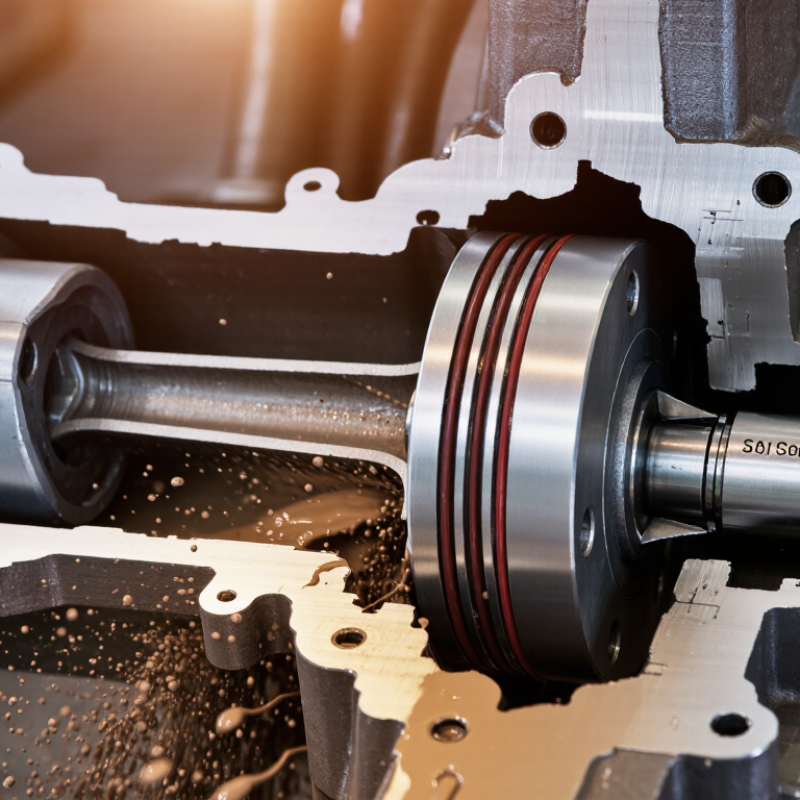
A mud pump piston is a replaceable sealing component that moves inside a matching liner in the pump’s fluid end. It is connected to a piston rod and travels back and forth as the crank mechanism turns. This reciprocating motion helps the pump draw drilling fluid in and force it out under pressure. The piston does not control flow alone; suction and discharge valves direct fluid through the pump.
Its main purpose is to help deliver a steady volume of drilling fluid into the drill string. The fluid cools and lubricates the bit, then returns through the annular space carrying rock cuttings. A close seal between piston and liner supports pressure and reduces fluid bypass. Wear, heat, abrasive solids, or poor fit can weaken that seal. A clean-looking piston can still be worn. Small scoring is easy to miss during a rushed inspection.
Tips: Check the piston and liner for cuts, uneven wear, or embedded grit during routine maintenance. Confirm the parts are compatible and installed according to equipment procedures. If pressure fluctuates or leakage appears, inspect the full fluid-end assembly rather than blaming the piston alone.
A mud pump piston is a sealing assembly that moves inside the pump’s fluid end. Its main parts are a central hub, a flexible sealing cup, and a retainer that holds the cup in position. The hub connects to the piston rod and transfers the rod’s motion. As the piston travels, the cup presses against the cylinder liner, helping draw drilling fluid in and push it out under pressure. Small gaps matter. A worn cup may leak, reduce pressure, or leave visible scoring on the liner.
Material choice depends on the mud, temperature, pressure, and operating hours. The hub is commonly steel, while the sealing cup may use rubber, polyurethane, or a fabric-reinforced elastomer. Nitrile compounds handle many oil- and water-based fluids; other elastomers may suit higher temperatures or more demanding chemical exposure. No material fits every job. A tougher cup can resist abrasion, yet may not seal as well when cold. That trade-off is easy to overlook. Inspect the cup for cuts, swelling, uneven wear, and hardening, and check that its retainer remains secure. Actual service life varies with fluid solids and operating conditions, so inspection records are more useful than assumptions.
What Is a Mud Pump Piston and How Does It Work?
How Piston Movement Generates Fluid Pressure
A mud pump piston moves back and forth inside a close-fitting liner. During the suction stroke, the piston retreats and pressure in the fluid chamber drops. The inlet valve opens, drawing drilling fluid into the chamber. Then the piston advances. The inlet valve closes, and the outlet valve opens as pressure rises. This repeated motion moves fluid into the discharge line. It is displacement, not the piston alone, that builds useful pressure; the valves and pump system matter too.
Tips: Check the piston and liner for scoring, cracks, or uneven wear. Look for leaks around the seal, and watch pressure readings for sudden changes. A worn seal can allow fluid to slip past the piston, reducing pumping efficiency. Follow the pump’s maintenance guidance, and isolate the equipment before inspection.
Each piston stroke delivers a pulse, so discharge flow is not perfectly smooth. A pulsation dampener can reduce pressure swings, but it cannot correct a damaged valve or poor seal. Mud also carries abrasive solids, which gradually wear contact surfaces. Real wear is not always uniform; one side may suffer more, and the cause may take careful inspection to identify.
A mud pump piston helps turn mechanical motion into the pressure that keeps drilling fluid moving. Driven back and forth inside a cylinder liner, it changes the chamber’s volume on each stroke. The piston works with inlet and discharge valves: fluid enters as the chamber expands, then leaves under pressure as the piston advances. The cycle repeats. That steady rhythm is essential, though the flow is not perfectly even.
From the pump, pressurized fluid travels down the drill string and exits through openings in the drill bit. It cools and cleans the bit, then returns to the surface through the space around the drill pipe, carrying rock cuttings with it. This circulation helps crews monitor the well and remove drilled material. The piston does not move the fluid alone; valves, liners, seals, and the drive system all affect how reliably the pump delivers it.
Small details matter. A worn seal may allow fluid to bypass the piston, reducing pressure and circulation. Uneven wear can also leave telltale marks on the liner. Operators check pressure readings and inspect components during maintenance, but readings alone do not reveal every problem. Mud is abrasive, and wear can develop gradually. It is easy to miss.
A mud pump piston moves back and forth inside the liner, while its sealing element helps contain drilling fluid under pressure. Repeated contact, abrasive solids, heat, and pressure cycles gradually wear the seal. Early clues include fluid leakage, unstable pressure, or a polished, flattened sealing edge. Small marks matter.
Inspect the piston after the pump is safely isolated and pressure is released. Clean off dried mud, then look for cuts, cracks, swelling, missing material, or uneven wear. Check the piston hub and liner for scoring or corrosion; a rough liner can quickly damage a new seal. Record the findings and operating hours, since one visual check rarely tells the whole story. In practice, inspection is not perfectly objective: technicians may disagree about whether a smooth wear band is acceptable.
Replacement depends on damage, service conditions, and the equipment’s specified limits, not just a fixed calendar interval. Confirm the replacement piston matches the liner dimensions and is suitable for the fluid, temperature, and pressure. During installation, keep sealing surfaces clean and avoid twisting or nicking the seal. Do not guess. After reassembly, restart under controlled conditions and watch for leakage or pressure changes before returning the pump to normal service.
Check for elastomer cracking or chunks missing, fluid bypass or leakage, reduced pressure or flow, uneven wear, and dimensional change. The 1–5 scores show qualitative inspection priority—not measured failure rates or universal replacement limits. Follow the pump and piston manufacturer’s specifications, and replace a piston when its condition no longer meets them.
„Thanks to the LUVIR technology, the solder resist process could be switched directly from the previously used mask exposure to direct exposure. As an outstanding digital solution on the market, this technology has been able to demonstrate fast process times and superior quality on our certified conventional ink in production. This allowed us to fully digitize the solder mask process at low cost – without process or ink adjustments. An excellent benefit to our production in Rot am See.“
Ralf Göhringer (Head of Production WE Rot am See)
I would definitely recommend the Limata machine and team for a future company purchase
Michael Greenaway
Compunetics Inc.
“The Limata ldi has been amazing!! Best thing we did was buy this machine”
Richard Brady
GM
Circuitlabs
“Since 2019, we have been running the Limata X1000 LDI system (including LUVIR for solder mask imaging) in daily production as an addition to our current process with film. The machine was capable of properly exposing Taiyo PSR-4000 BN (DI) solder mask types on normal to high-copper boards using a new and unique direct imaging process. The machine operating interface is very user friendly which allowed for a quick technical training curve. The pre-registration processing reduced several seconds of production time at every print. Limata support and service staff is incomparable. They supported our team every step of the way at basically any time of the day or night, with literally, an immediate response time, customizing the software interface to best fit our Operations and needs.
We have exposed more than 8,000 prints since end of October, on various solder mask colors and some resist film panels. Limata, has proven to be very capable and innovative. They are a strong contender in the industry.
We have very much enjoyed this project, and working with the team!
Thank you Limata for the continued support and being a part of our growth.”
Bill Sezate
Vice President, GM
Summit Interconnect
As a replacement to our current contact exposure process with film, the LIMATA X2000 system including LUVIR-Technology was capable of properly exposing non-LDI solder mask types using a direct imaging process. The machine offers cutting edge software with a very intuitive operating interface which allowed for quick technician training curve. The dual drawer system combined with pre-registration processing reduced several seconds of production time at every machine cycle. Limata support and service staff is world class. They added software patches to keep production running at shortest possible response times, customized the software interface to best fit our in-house Operations system, and even wrote a step-by-step machine processing manual. As a result of the project, we have exposed more than 16,000 times on various product types and solder mask brands/colors. Limata, in a very short timeframe as a company, has definitely shown they are truly innovative and will be challenging the industry of direct imaging for the top spot.
Kevin Beattie
Process Engineer
TTM Technologies
Forest Grove Division
