Buying an oil-immersed electric transformer is a long-term engineering decision, not just a price comparison. A unit may sit outdoors for decades, exposed to heat, rain, dust, and changing loads. Its oil helps insulate and cool the windings, but performance depends on sound design, materials, installation, and maintenance. Small details matter.
The International Energy Agency’s Electricity Grids and Secure Energy Transitions (2023) estimates that more than 80 million kilometers of electricity grids may need to be added or refurbished by 2040. It also says annual grid investment must rise above $600 billion by 2030 to meet transition needs. These are system-wide figures, not forecasts for transformer sales. Still, they show why buyers should check capacity, losses, and future expansion plans before choosing equipment. An Electric Transformer Oil-Immersed Transformer should match the site’s voltage, load profile, ambient conditions, and protection requirements.
This guide outlines seven practical checks: ratings, efficiency, insulation and oil specifications, cooling, safety features, supplier quality, and lifecycle support. Request test records and clarify which standards apply to your project; do not rely on a brochure alone. Ask how the supplier handles oil sampling, spare parts, and service response. Then compare total ownership costs, not only the quoted price. A checklist helps, but it cannot replace a qualified engineer’s review. And, honestly, a low purchase price can look attractive until operating losses or delayed service appear.
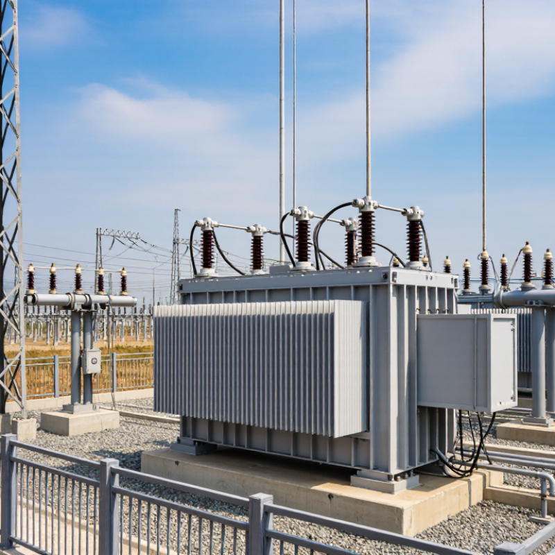
Before sizing an oil-immersed transformer, list the actual loads, not just the total connected rating. Record each load’s voltage, phase, running current, and starting demand. Motors can draw several times their normal current briefly. That surge matters. Include expected additions, but avoid padding the estimate without evidence. A load forecast is never perfect.
The U.S. Department of Energy’s 2016 distribution-transformer analysis estimated that these transformers account for about 2.5% of U.S. electricity use, or roughly 61 billion kilowatt-hours annually. That fleet-wide figure shows why efficient, correctly matched equipment matters; it does not predict one site’s losses. Confirm the utility’s primary voltage and the required secondary voltage, including acceptable tap settings. Then verify frequency. A 50 Hz unit is not automatically suitable for a 60 Hz supply, or vice versa; check its nameplate and manufacturer’s rated voltage-frequency combinations against IEC 60076 or IEEE C57.12.00 requirements. Ask the supplier to confirm the rating in writing. Also provide the site’s highest continuous load and motor-starting details, so sizing reflects operating conditions rather than a neat spreadsheet total.
Confirm load, voltage, and 50/60 Hz requirements before sizing the transformer.
Why frequency matters: At the same voltage, volts per hertz is 20% higher at 50 Hz than at 60 Hz (480 ÷ 50 = 9.6 V/Hz; 480 ÷ 60 = 8.0 V/Hz). This comparison illustrates why the transformer’s rated voltage and frequency must match the supply. Confirm the actual load in kVA and required primary and secondary voltages with the manufacturer before selecting a unit.
When comparing oil-immersed distribution transformers, check the applicable DOE efficiency minimum under 10 CFR Part 431. The requirement depends on the transformer’s category and rating, so compare the exact configuration—not a nearby model. Ask for documentation showing the applicable standard and efficiency test results. Details matter.
Compare units tested on the same basis. Review rated kVA, voltage, phase, and efficiency alongside no-load and load losses. A small difference in losses can affect operating costs over years of continuous service. For a practical check, match the nameplate data to your expected load, then ask how the quoted efficiency relates to the DOE minimum. Do not rely on a broad claim such as “high efficiency.”
A transformer that clears the minimum may still cost more to operate than a better-matched option. Estimate energy costs using your actual load profile and local electricity rates, rather than assuming full load all day. Request the test method and supporting records, and confirm that the supplier’s figures apply to the unit being quoted. Paper comparisons can look neat. Real loads are less tidy, and I may be overlooking site-specific factors such as future expansion or seasonal demand. Those assumptions deserve a second look.
For many oil-immersed transformers, IEC 60076-2 specifies temperature-rise limits of 60 K for oil and 65 K for average winding temperature, subject to the applicable design and test conditions. These are rises above ambient, not maximum operating temperatures. A 60 K oil rise does not mean the oil should reach 60°C. Small detail, big difference.
Tip: Ask for the temperature-rise test report. Check the stated cooling method, ambient conditions, and measurement method against the transformer’s rating and the relevant standard edition. The winding figure is generally determined by resistance measurement, so it may not match a single surface thermometer reading. Look closely at the test assumptions.
A unit that meets these limits has demonstrated performance under defined conditions, but installation still matters. Restricted airflow, blocked radiators, or sustained overload can push temperatures higher in service. I would not judge a purchase from one number alone; review the test data and site conditions together. Ambient temperatures vary, and that part is easy to underestimate.
| Tip | What to Check | Practical Requirement | Evidence to Request |
|---|---|---|---|
| 1 | Confirm temperature-rise limits | For applicable liquid-immersed transformer designs, IEC 60076-2 gives commonly specified limits of 60 K top-liquid temperature rise and 65 K average winding temperature rise. A kelvin rise has the same numerical size as a Celsius-degree rise. | Request the guaranteed temperature-rise values, the specified cooling method, and the applicable IEC 60076-2 edition. Confirm that the limits match the transformer’s design and purchase specification. |
| 2 | Check the rating and cooling arrangement | Match the nameplate rating and cooling designation—such as ONAN or ONAF—to the expected load and site conditions. Do not assume a forced-cooling rating is available when fans or pumps are out of service. | Review the rating plate, cooling-system description, cooling-stage ratings, and the conditions under which each rating is permitted. |
| 3 | Review the temperature-rise test | Temperature-rise verification is based on the applicable standard test method and specified test conditions. The measured result should be assessed against the agreed guaranteed limits, not against an unrelated operating-temperature figure. | Request the routine or type-test documentation required by the contract, including test method, cooling condition, ambient or reference conditions, and reported oil and winding results. |
| 4 | Account for ambient temperature and altitude | Site ambient temperature and installation altitude can affect thermal performance and cooling. State the expected minimum, maximum, and average ambient conditions, as well as site altitude, in the procurement specification. | Ask for confirmation that the guaranteed rating and temperature-rise performance apply to the stated site conditions, or for any required derating or design adjustment. |
| 5 | Specify the insulating liquid | Identify the required liquid type and applicable quality requirements. Mineral oil and alternative insulating liquids can have different properties; verify compatibility with the transformer design and operating conditions. | Request the liquid specification and relevant test or quality records, including confirmation that the liquid is suitable for the equipment and the intended service. |
| 6 | Check protection and temperature monitoring | Confirm the proposed provisions for liquid-level indication, pressure relief, and temperature indication or alarms. Alarm and trip settings should be coordinated with the design and operating procedures rather than inferred from temperature-rise limits alone. | Review the protection and instrument list, alarm/trip schedule, wiring or control documentation, and the specified method for monitoring winding temperature. |
| 7 | Clarify the scope and acceptance criteria | Temperature-rise limits are rises above the applicable reference ambient, not fixed absolute oil or winding temperatures. Agree the standard edition, guaranteed values, test scope, tolerances, and documentation before placing the order. | Include the agreed IEC 60076 requirements, temperature-rise guarantees, inspection and test plan, acceptance criteria, and required reports in the purchase documents. |
Note: The 60 K and 65 K figures are commonly used IEC 60076-2 temperature-rise limits for applicable designs; confirm the precise requirements against the specified standard edition, transformer construction, cooling method, and contract.
Tip 1: Ask for the oil’s certificate of analysis and confirm it meets IEC 60296:2020 for unused mineral insulating oils. Check the oil type, delivery date, water content, acidity, and breakdown voltage. Values must match the stated oil category and test conditions; a single “pass” is not enough.
Tip 2: Require test methods alongside results. IEC 60156 covers power-frequency breakdown voltage, while IEC 60814 measures water content by Karl Fischer titration. Compare results with the supplier’s limits and applicable acceptance guidance, such as IEEE C57.106. Take a sealed sample from the delivered batch, not an unlabeled bottle. Appearance can mislead.
Tip 3: Keep the report with the transformer’s commissioning records. CIGRE Technical Brochure 445, Guide for Transformer Maintenance, treats oil diagnostics as part of condition-based maintenance. Ask the seller to explain any borderline result and retest if sampling or storage is uncertain. A clean sample cannot prove every part of the transformer is sound; that distinction is easy to overlook.
An oil-immersed transformer may look immaculate, yet its test sheet tells a deeper story. Ask for routine-test results linked to the unit’s serial number and nameplate ratings. The transformation-ratio test should cover the specified tap positions, with phase displacement and vector group recorded. A mismatch can affect parallel operation. Check the figures, not just the pass stamp.
Losses and impedance deserve close attention. No-load loss and current indicate core performance; load loss and short-circuit impedance help confirm winding design and expected voltage drop. Compare measured values with the purchase specification, allowing for stated test conditions and tolerances. Small differences matter. A vague report is not reassuring.
For insulation, review the dielectric routine tests, including applied-voltage and induced-voltage withstand results, as applicable to the design. Confirm test levels and outcomes are documented, rather than relying only on a general “insulation passed” note. Ask how the report identifies the tested winding connections and tap setting. Paperwork can be tidy but incomplete; I would pause over missing details and request clarification before accepting the unit.
„Thanks to the LUVIR technology, the solder resist process could be switched directly from the previously used mask exposure to direct exposure. As an outstanding digital solution on the market, this technology has been able to demonstrate fast process times and superior quality on our certified conventional ink in production. This allowed us to fully digitize the solder mask process at low cost – without process or ink adjustments. An excellent benefit to our production in Rot am See.“
Ralf Göhringer (Head of Production WE Rot am See)
I would definitely recommend the Limata machine and team for a future company purchase
Michael Greenaway
Compunetics Inc.
“The Limata ldi has been amazing!! Best thing we did was buy this machine”
Richard Brady
GM
Circuitlabs
“Since 2019, we have been running the Limata X1000 LDI system (including LUVIR for solder mask imaging) in daily production as an addition to our current process with film. The machine was capable of properly exposing Taiyo PSR-4000 BN (DI) solder mask types on normal to high-copper boards using a new and unique direct imaging process. The machine operating interface is very user friendly which allowed for a quick technical training curve. The pre-registration processing reduced several seconds of production time at every print. Limata support and service staff is incomparable. They supported our team every step of the way at basically any time of the day or night, with literally, an immediate response time, customizing the software interface to best fit our Operations and needs.
We have exposed more than 8,000 prints since end of October, on various solder mask colors and some resist film panels. Limata, has proven to be very capable and innovative. They are a strong contender in the industry.
We have very much enjoyed this project, and working with the team!
Thank you Limata for the continued support and being a part of our growth.”
Bill Sezate
Vice President, GM
Summit Interconnect
As a replacement to our current contact exposure process with film, the LIMATA X2000 system including LUVIR-Technology was capable of properly exposing non-LDI solder mask types using a direct imaging process. The machine offers cutting edge software with a very intuitive operating interface which allowed for quick technician training curve. The dual drawer system combined with pre-registration processing reduced several seconds of production time at every machine cycle. Limata support and service staff is world class. They added software patches to keep production running at shortest possible response times, customized the software interface to best fit our in-house Operations system, and even wrote a step-by-step machine processing manual. As a result of the project, we have exposed more than 16,000 times on various product types and solder mask brands/colors. Limata, in a very short timeframe as a company, has definitely shown they are truly innovative and will be challenging the industry of direct imaging for the top spot.
Kevin Beattie
Process Engineer
TTM Technologies
Forest Grove Division
