Selecting the right Cartridge Filter Housing affects filtration performance, maintenance time, and long-term operating costs. The choice is rarely as simple as matching a pipe size. A housing must handle the fluid, pressure, temperature, flow rate, and cleaning routine used in your facility. Small details matter.
This guide presents ten practical tips for evaluating a Cartridge Filter Housing before purchase. It examines housing materials, cartridge compatibility, micron ratings, sealing methods, connection types, and pressure-drop data. It also considers installation space, replacement access, and the risks of choosing an undersized unit. A stainless steel housing may suit demanding industrial service, while polypropylene can be practical for selected chemical or water applications. The correct decision depends on verified operating conditions, not assumptions.
Experienced technicians often inspect the housing body, gasket seat, clamps, and vent design before approving a system. They also compare manufacturer datasheets with actual site requirements. That step can expose impressive-looking specifications that do not fit real workloads. No selection is perfect. Flow may change. Fluids may behave differently during temperature shifts. A useful evaluation leaves room for these uncertainties and records the reasons behind each decision. Where hygiene, pressure safety, or process quality matters, qualified professionals should review applicable standards and supplier documentation. Reliable suppliers should explain testing, traceability, replacement parts, and service limitations clearly. These ten tips aim to support a careful, evidence-based choice, helping readers avoid expensive surprises after installation.
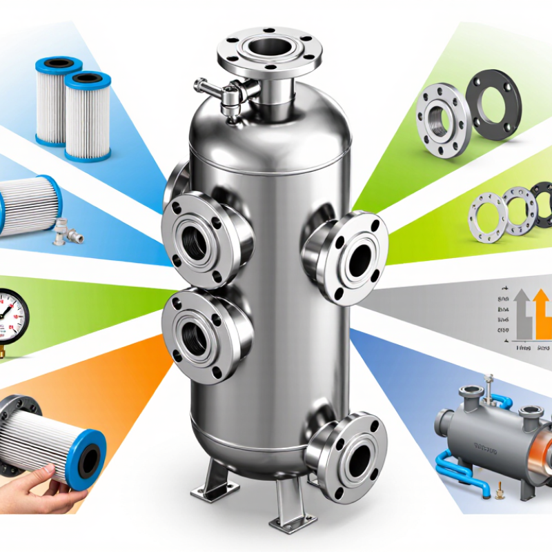
Choosing a cartridge filter housing starts with the fluid, not the catalog.
Record pH, viscosity, density, suspended solids, and chemical compatibility. Water at 20°C behaves differently from oil at 80°C. Housing materials, seals, and cartridge media must tolerate the real operating temperature, not the laboratory value. The U.S. EPA’s 2023 Water Reuse Action Plan emphasizes monitoring source-water variability because changing conditions can undermine treatment performance. Measure it continuously when practical.
Flow rate needs a design margin, but excessive margin can create poor filtration economics. Calculate normal, peak, and startup flow separately. A cartridge rated at 100 L/min may perform differently at higher viscosity or rising pressure drop. The ISO 16889 multipass method uses beta ratios to describe particle-removal performance, yet this test does not reproduce every plant condition. That distinction matters. Real installations are less tidy than spreadsheets.
Contaminant load determines service life. Identify particle size, concentration, shape, and whether solids are sticky or compressible. The WHO Guidelines for Drinking-water Quality, 2022, recommend turbidity below 1 NTU where feasible, but industrial fluids may require far stricter particle control. Ask for a loading curve, not only a micron rating. A 5-micron claim alone is incomplete. Track differential pressure during a trial run, then compare it with the supplier’s stated changeout limit. I would also repeat testing after temperature changes; this step is often missed, and that omission can distort the final housing selection.
Choosing a Cartridge Filter Housing: Set Micron Targets Using ISO 16889 Beta Ratios and 99.9% Efficiency
A cartridge housing should match a measured contamination risk, not a convenient micron label. ISO 16889:2021 defines the multi-pass test for hydraulic filter performance. It uses the beta ratio to compare upstream and downstream particle counts. The formula is βx = particles upstream ÷ particles downstream at size x.
For example, β10 = 1,000 means one particle passes for every 1,000 particles entering. That equals 99.9% efficiency at 10 microns. β10 = 200 provides 99.5% efficiency, not 99.9%. The difference matters in servo valves, bearings, and tight-clearance pumps. Small numbers can hide large risks.
Check the fluid’s ISO 4406 cleanliness target before selecting the housing. This standard reports particle levels at 4, 6, and 14 microns. Then confirm the filter’s tested beta ratings at those particle sizes. Do not treat “10 micron” as proof of absolute filtration. It may describe a nominal rating with limited test control.
Flow capacity needs equal attention. A crowded element raises pressure loss and can trigger bypass flow. Measure the fluid temperature, viscosity, dirt loading, and service interval. Select a housing with enough area for cold starts and peak flow.
Field experience is less perfect. Particle counters can drift, samples can be contaminated, and laboratory results may not represent real cycling. Review ISO 16889 data, installation records, and differential-pressure trends together. The most expensive mistake is trusting one impressive number.
| Tip | Selection Dimension | What to Check | Practical Target or Formula | Why It Matters |
|---|---|---|---|---|
| 1 | Define the contaminant and its risk | Identify whether the target is dirt, rust, process solids, catalyst fines, microorganisms, or another contaminant. | Specify particle type, concentration, shape, and allowable downstream loading. | Micron size alone does not describe particle hardness, density, compressibility, or the damage it may cause. |
| 2 | Set the nominal or absolute micron basis | Confirm whether the supplier’s micron rating is nominal, absolute, or associated with a defined test method. | Use an ISO 16889 beta rating when a quantified particle-removal target is required. | Different rating conventions can produce substantially different results at the same stated micron size. |
| 3 | Translate efficiency into a beta ratio | Use the ISO 16889 multi-pass particle-counting relationship at the selected particle size. | Efficiency = 1 − 1/β 99.0% = βx 100 99.9% = βx 1,000 | A beta ratio gives a numerical basis for comparing filtration performance rather than relying on a vague “fine filter” description. |
| 4 | Choose the particle-size test point | Check the subscript in βx, where x represents the particle size in micrometres used for the rating. | Example: β10 ≥ 1,000 means at least 99.9% efficiency for particles measured at 10 µm under the stated test conditions. | β10 does not automatically prove β5 or β20 performance. The test size must match the process risk. |
| 5 | Balance protection and pressure drop | Compare clean pressure drop, allowable final pressure drop, fluid viscosity, and operating temperature. | Select a housing and element combination that remains within the equipment’s pressure-drop limit at maximum flow. | A tighter filter may improve particle removal but can increase energy use and shorten service life if undersized. |
| 6 | Size for flow and viscosity | Use maximum, normal, and minimum flow rates together with the fluid’s operating viscosity and density. | Size from the element’s verified flow-versus-pressure-drop data, not from connection size alone. | High-viscosity fluids generally create higher pressure drop and may require more filtration area or a larger housing. |
| 7 | Verify pressure and temperature ratings | Check maximum allowable working pressure, design temperature, differential-pressure rating, and any derating requirements. | The housing rating must exceed the highest credible operating and upset conditions. | Pressure and temperature limits apply to the complete assembly, including seals, clamps, covers, and element supports. |
| 8 | Match materials and seal compatibility | Review fluid chemistry, pH, solvents, oxidizers, temperature, and cleaning or sanitization chemicals. | Confirm wetted-material and seal compatibility using documented chemical-resistance data. | Material incompatibility can cause swelling, embrittlement, corrosion, leakage, or contamination of the process fluid. |
| 9 | Plan installation and maintenance | Check element length, closure type, orientation, drain and vent locations, access clearance, and replacement procedure. | Provide isolation, depressurization, venting, draining, and a differential-pressure monitoring point where appropriate. | Safe access and reliable change-out procedures reduce downtime and prevent exposure to trapped pressure or hazardous fluids. |
| 10 | Request complete performance documentation | Ask for the test method, beta ratio, rated particle size, flow conditions, test fluid, pressure-drop data, and material specifications. | For a 99.9% target, specify βx ≥ 1,000 at the selected x-micrometre test point and verify application suitability. | Documented test conditions make performance claims traceable and prevent direct comparison of incompatible ratings. |
Choosing a cartridge filter housing starts with the process, not the vessel. A cartridge that fits the housing can still perform poorly. Flow rate, fluid temperature, solids loading, and viscosity all influence sizing. Record these values during normal operation, not only under ideal conditions. Small details matter.
Pressure drop is a practical sizing signal. Select a cartridge with a low clean pressure drop at the required flow. Leave room for loading before the system reaches its allowable differential pressure. A gauge on both sides of the housing helps operators see this change. Dirt capacity also matters. Two cartridges with the same micron rating may hold very different amounts of sediment. Review test data, then compare it with your actual contamination profile. Laboratory results are useful, but they are not the whole story.
Viscous liquids need special attention. As temperature falls, viscosity can rise sharply, increasing pressure drop and reducing flow. Use correction data for the actual fluid and operating temperature. Oversizing the cartridge area often provides steadier service and fewer changeouts. However, excessive area can hide poor process control and increase maintenance cost. I have seen designs based on average flow fail during cold starts. That mistake is easy to repeat. A small pilot test, with recorded pressure readings and cartridge weight before and after use, can reveal the real dirt capacity. Check the numbers again after installation.
Start by confirming the housing’s wetted components are genuine 316L stainless steel. Ask for material certificates and, when practical, request positive material identification. Do not rely on polished appearance alone. Check weld quality, internal finish, crevices, and drain design. These details affect corrosion resistance and cleaning performance. Confirm the cartridge length, diameter, end configuration, and required flow rate. A small mismatch can cause bypass or difficult installation. I have seen specifications copied incorrectly between projects, so verify every dimension against the actual cartridge.
Review seal compatibility with the process fluid, temperature, and cleaning chemicals. EPDM, silicone, and fluoropolymer seals behave differently. Consider swelling, compression set, extraction, and repeated thermal cycles. A seal may perform well during production but fail during sanitation.
Check the housing’s maximum working pressure and temperature together, not separately. Ratings often decrease as temperature rises. Include start-up surges, differential pressure, vacuum conditions, and blocked-filter scenarios. Add suitable monitoring and pressure relief where the process requires it. Keep a safety margin, but avoid choosing an oversized housing without evidence.
Request pressure-test records, surface-finish data, and clear inspection documents. Confirm connections suit your piping and maintenance tools. Check whether the closure can be opened safely after pressure release. Consider installation space, cartridge change time, and operator access. I once focused too heavily on material grade and overlooked awkward clamp access. That mistake increased maintenance time. Recheck the complete specification with operations and quality staff before purchase.
Choosing a cartridge filter housing involves more than matching pipe size. Confirm whether the cartridge uses a DOE or SOE connection before ordering. A DOE cartridge needs compatible end gaskets and proper compression. An SOE cartridge requires the correct adapter, seal, and seating depth. Small dimensional errors can cause bypass or difficult installation.
For food, beverage, or pharmaceutical service, request material declarations and test records for applicable 21 CFR requirements. Do not accept “FDA compliant” as a complete answer. Ask which components were evaluated, including seals, plastics, and lubricants. For potable water, check NSF/ANSI 61 certification or documentation for wetted materials. Certification scope matters. It may cover only specific sizes or operating conditions. I have seen projects delayed because a housing certificate did not match the selected gasket material.
Maintenance access deserves equal attention. Leave enough clearance to remove the bowl, lift the cartridge, and inspect the sealing surfaces without awkward tools. A drain port can reduce spills, while a pressure gauge helps confirm loading before flow collapses. Use a housing with a visible identification plate and accessible replacement parts. Record cartridge changes, pressure readings, and sanitation activities. These details support reliable operation and traceability.
One mistake is common: choosing the smallest housing to reduce purchase cost. That decision can increase pressure drop and replacement frequency. I still recheck access dimensions on every installation. Drawings are useful, but field obstacles are real.
Check DOE/SOE fit, 21 CFR compliance, NSF/ANSI 61, and maintenance access before specifying a housing.
The chart shows whether each selection checkpoint is applicable to three common service contexts. A value of 1 means the checkpoint should be reviewed; 0 means it is not generally the defining requirement for that context. DOE/SOE compatibility and maintenance access are mechanical or operational checks, while 21 CFR and NSF/ANSI 61 depend on the intended contact and water-use application. Also verify cartridge length, pressure and temperature ratings, wetted materials, seal compatibility, housing configuration, replacement access, and spare-part availability.
„Thanks to the LUVIR technology, the solder resist process could be switched directly from the previously used mask exposure to direct exposure. As an outstanding digital solution on the market, this technology has been able to demonstrate fast process times and superior quality on our certified conventional ink in production. This allowed us to fully digitize the solder mask process at low cost – without process or ink adjustments. An excellent benefit to our production in Rot am See.“
Ralf Göhringer (Head of Production WE Rot am See)
I would definitely recommend the Limata machine and team for a future company purchase
Michael Greenaway
Compunetics Inc.
“The Limata ldi has been amazing!! Best thing we did was buy this machine”
Richard Brady
GM
Circuitlabs
“Since 2019, we have been running the Limata X1000 LDI system (including LUVIR for solder mask imaging) in daily production as an addition to our current process with film. The machine was capable of properly exposing Taiyo PSR-4000 BN (DI) solder mask types on normal to high-copper boards using a new and unique direct imaging process. The machine operating interface is very user friendly which allowed for a quick technical training curve. The pre-registration processing reduced several seconds of production time at every print. Limata support and service staff is incomparable. They supported our team every step of the way at basically any time of the day or night, with literally, an immediate response time, customizing the software interface to best fit our Operations and needs.
We have exposed more than 8,000 prints since end of October, on various solder mask colors and some resist film panels. Limata, has proven to be very capable and innovative. They are a strong contender in the industry.
We have very much enjoyed this project, and working with the team!
Thank you Limata for the continued support and being a part of our growth.”
Bill Sezate
Vice President, GM
Summit Interconnect
As a replacement to our current contact exposure process with film, the LIMATA X2000 system including LUVIR-Technology was capable of properly exposing non-LDI solder mask types using a direct imaging process. The machine offers cutting edge software with a very intuitive operating interface which allowed for quick technician training curve. The dual drawer system combined with pre-registration processing reduced several seconds of production time at every machine cycle. Limata support and service staff is world class. They added software patches to keep production running at shortest possible response times, customized the software interface to best fit our in-house Operations system, and even wrote a step-by-step machine processing manual. As a result of the project, we have exposed more than 16,000 times on various product types and solder mask brands/colors. Limata, in a very short timeframe as a company, has definitely shown they are truly innovative and will be challenging the industry of direct imaging for the top spot.
Kevin Beattie
Process Engineer
TTM Technologies
Forest Grove Division