China has become a significant base for industrial Laser Cladding equipment, supported by strong manufacturing capacity and expanding repair demand. Applications now include turbine blades, hydraulic cylinders, mining rollers, and oilfield components. These parts often face abrasive wear, corrosion, or heat damage.
Industry reports indicate sustained growth. MarketsandMarkets’ research on laser cladding equipment identifies aerospace, energy, and automotive industries as key demand sectors. Grand View Research also reports that broader laser processing markets are expanding through automation and high-power fiber lasers. However, published estimates differ because some studies measure equipment only, while others include services, powders, software, and refurbishment.
That difference matters.
This article presents China’s top 10 Laser Cladding machine manufacturers through practical criteria. These criteria include laser source quality, powder-feeding stability, motion accuracy, cooling design, process monitoring, and after-sales support. A machine may look impressive in a showroom but produce inconsistent tracks after several hours of operation. Real performance appears on curved blades, narrow grooves, and large cylindrical surfaces.
Technical credibility requires more than a product catalogue. We consider documented case studies, material compatibility, system integration, safety certifications, and evidence of repeatable results. Customer training also deserves attention, especially when operators adjust laser power, scanning speed, powder flow, and overlap rates.
No ranking is permanently correct. Supplier capabilities change, and some public data remain incomplete. Therefore, readers should verify test reports, inspect sample parts, and request production references before purchasing. The strongest manufacturer is not always the largest one. It is the partner that can deliver stable deposition, measurable savings, and dependable service over time.
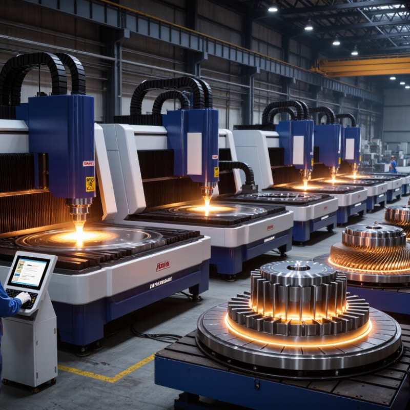
China Top 10 Laser Cladding Machine Manufacturers
Laser cladding builds a metallurgical coating by feeding powder into a focused laser melt pool. Typical deposited layers range from 0.2 to 2.0 mm. Thin layers suit precision repair, while thicker passes support worn shafts, rolls, and hydraulic components. The final result depends on laser power, scanning speed, powder feed rate, spot size, and stand-off distance.
Dilution below 10% is a useful target for many surface-engineering projects. It means limited mixing between the coating and substrate. Low dilution can protect the powder’s designed chemistry. However, it must not weaken bonding. Cross-sectional measurement remains essential. A shiny track proves little.
Not enough.
Technicians should cut, mount, polish, and etch a sample before approving production settings. They can then measure coating height, fusion depth, pores, cracks, and hardness. Overlap between adjacent tracks also matters. Excessive overlap may create heat accumulation and distortion. Insufficient overlap can leave grooves.
When evaluating China’s top ten laser cladding machine manufacturers, buyers should request actual process data, not only catalog specifications. Ask for test coupons using the intended alloy and substrate. Review powder utilization, layer consistency, thermal control, and maintenance access. A machine may achieve 2.0 mm layers, yet struggle with stable 0.2 mm deposits. That gap deserves careful reflection. Process flexibility often matters more than maximum advertised power.
This chart presents representative laser cladding process targets rather than company or brand data. Layer thickness values span 0.2–2.0 mm, while the corresponding dilution targets remain below the commonly specified 10% limit.
When comparing China’s top 10 laser cladding machine manufacturers, do not judge power by its headline number. A 2,000-watt source may perform poorly if the beam profile is unstable. Ask for measured output, spot-size data, cooling details, and continuous operation records. Request a sample cladding test using your actual alloy and part geometry. A polished brochure proves little.
Accuracy appears in the finished layer. Check powder-feeding consistency, motion repeatability, torch alignment, and temperature control. Ask for inspection reports showing thickness variation and dilution levels. A practical trial should include curved surfaces, edges, and several hours of operation. Flat coupons can hide weaknesses. Deposition rate also needs careful interpretation. Kilograms per hour sound impressive, but excessive heat may increase dilution, distortion, or post-machining work. Material recovery matters too. Less powder waste can lower real production costs.
Warranty terms deserve the same attention as technical specifications. Confirm coverage for the laser source, powder feeder, motion system, and control software. Clarify response times, spare-part availability, installation support, and operator training. Insist on written acceptance criteria before payment. Some promises remain vague. That is a warning sign. A remote demonstration is useful, but it cannot replace an independent test. My assessment would remain provisional until the machine completes a repeatable production trial under documented conditions.
China’s top ten laser cladding machine manufacturers are not identical in engineering depth. Their core technologies often include high-power fiber lasers, coaxial powder feeding, and robotic motion control. These systems can rebuild worn shafts, seal surfaces, molds, and industrial rollers with controlled heat input.
Shop-floor evidence matters more than polished brochures. Experienced suppliers combine laser beam shaping with real-time temperature monitoring. Some use closed-loop control to adjust powder flow, travel speed, and laser power during deposition. This helps reduce dilution, pores, cracks, and uneven layer thickness. Many platforms support iron-, nickel-, and cobalt-based powders for different wear and corrosion conditions. Their machines may also integrate CNC tables, six-axis robots, automatic focusing, and multi-axis path planning.
Reliable evaluation requires more than a machine demonstration. Buyers should review sample reports, material traceability, repeatability tests, and maintenance records. Numbers need context. A claimed deposition rate may change with powder size, alloy type, layer thickness, and operator experience. Several manufacturers provide process databases and parameter libraries, but these resources are not always equally mature. A few published figures also need independent verification. That gap deserves attention.
Engineers should inspect finished cross-sections, not only shiny surfaces. Hardness maps, bonding strength, dimensional accuracy, and post-machining allowance reveal practical performance. Training quality matters too. Even advanced equipment can produce inconsistent results when calibration, powder drying, or substrate preparation is neglected.
| Rank | Manufacturer Profile | Primary Cladding Technology | Typical Laser Source | Typical Power Range | Compatible Materials | Core Process Technology | Typical Applications |
|---|---|---|---|---|---|---|---|
| 1 | Profile A | High-speed laser cladding | Fiber laser, 1,070 nm class | 2–12 kW | Nickel alloys, cobalt alloys, iron-based powders, carbide composites | Coaxial powder feeding with closed-loop temperature monitoring | Rolls, hydraulic rods, shafts, wear-resistant surfaces |
| 2 | Profile B | Precision laser metal deposition | Single-mode or multi-mode fiber laser | 1–6 kW | Stainless steel, tool steel, nickel-based alloys, titanium alloys | Multi-axis CNC motion with programmable powder flow | Mold repair, die repair, edge rebuilding, small-batch components |
| 3 | Profile C | Laser cladding for large components | High-power fiber laser | 6–20 kW | Iron-based alloys, nickel alloys, tungsten carbide blends | Wide-area deposition and synchronized rotary-axis control | Mining rollers, large shafts, construction components, energy equipment |
| 4 | Profile D | Laser surface alloying and hardfacing | Continuous-wave fiber laser | 2–10 kW | Cobalt alloys, nickel alloys, stainless steel, carbide powders | Low-dilution deposition with inert-gas shielding | Valves, pump parts, turbine components, sealing surfaces |
| 5 | Profile E | Robot-integrated laser cladding | Fiber laser, 1,070 nm class | 1–6 kW | Carbon steel, stainless steel, nickel alloys, cobalt alloys | Six-axis robotic motion with offline path programming | Complex curved parts, repair cells, agricultural and engineering machinery |
| 6 | Profile F | Hybrid additive and subtractive repair | Fiber laser integrated with CNC machining | 2–8 kW | Tool steel, stainless steel, nickel alloys, aluminum alloys | In-process deposition followed by turning or milling | Mold restoration, dimensional recovery, precision remanufacturing |
| 7 | Profile G | High-hardness wear-resistant cladding | High-power diode or fiber laser | 4–15 kW | Chromium carbide, tungsten carbide, iron-based hardfacing powders | Controlled overlap and multilayer deposition | Crusher parts, wear plates, cutting tools, conveying components |
| 8 | Profile H | Aerospace and energy-component cladding | Precision fiber laser | 1–4 kW | Titanium alloys, nickel-based superalloys, stainless steel | Argon shielding, melt-pool monitoring, low-dilution repair | Blades, casings, turbine parts, high-value repair components |
| 9 | Profile I | Large-format laser deposition | Multi-kilowatt fiber laser | 8–25 kW | Carbon steel, low-alloy steel, nickel alloys, stainless steel | Large working envelope with automated height compensation | Wind-power parts, marine shafts, petrochemical equipment, heavy machinery |
| 10 | Profile J | Compact laser repair and remanufacturing | Air-cooled or water-cooled fiber laser | 0.5–3 kW | Tool steel, stainless steel, nickel alloys, copper-based alloys | Fine powder delivery with vision-assisted positioning | Small molds, precision tools, gear teeth, localized surface repair |
Note: Manufacturer identities and brand-specific data are intentionally omitted. Technical ranges represent commonly used configurations in industrial laser cladding and laser metal deposition systems.
China’s top laser cladding machine manufacturers are often compared by laser power, accuracy, and automation. Systems from 1 to 20 kW cover different repair and coating tasks. Lower power suits thin layers and small parts. Higher power supports large shafts, rolls, and heavy industrial components. However, power alone does not prove productivity.
A claimed accuracy of ±0.05 mm needs careful examination. Thermal distortion, powder quality, fixturing, and scanning strategy can change real results. In practical evaluations, request sample data from similar materials and geometries. Check bead width, dilution rate, surface roughness, and repeatability. Automated powder feeding and robotic path planning can reduce operator variation. Closed-loop monitoring may improve consistency, but sensors require calibration. The impressive specification is not always the shop-floor result.
Tips: Compare complete process cells, not only laser sources. Ask for measured accuracy after several continuous cycles. Inspect nozzle replacement time, software controls, safety interlocks, and maintenance access. A factory acceptance test should use your actual alloy and component shape. Smaller 1–6 kW systems may be easier to control, while 10–20 kW equipment can demand stronger cooling and ventilation. I would avoid choosing by power ranking alone; that approach is simple, but sometimes wrong.
Laser cladding machines support mold repair, shaft rebuilding, valve restoration, and wear protection for mining rollers. In practical workshops, operators often restore a damaged edge before machining it back to size. The process can reduce heat distortion compared with conventional welding. However, results depend heavily on powder selection, laser stability, and surface preparation.
Small errors matter.
Material compatibility requires more than matching powder to substrate. Nickel, iron, and cobalt alloys suit different wear, corrosion, and temperature conditions. Carbide-reinforced powders may improve abrasion resistance, but they can increase cracking risks. Operators should check dilution, thermal expansion, hardness, and required machining allowance.
A test coupon is essential. It exposes problems earlier.
Certification should be verified, not merely listed in a brochure. Ask for quality-system records, electrical safety documentation, laser-safety compliance, and relevant CE or equivalent certificates. Confirm issuing bodies and certificate scope.
Machine selection should include laser power, powder-feeding accuracy, worktable size, optical protection, cooling design, and control software. Request measured deposition rates, repeatability data, maintenance intervals, and sample-cladding reports.
Installation training and local technical support also affect real production costs. A lower purchase price may hide difficult calibration and costly downtime.
One lesson deserves attention: impressive specifications do not guarantee a stable bead. Witness testing on your material is still the most reliable comparison.
„Thanks to the LUVIR technology, the solder resist process could be switched directly from the previously used mask exposure to direct exposure. As an outstanding digital solution on the market, this technology has been able to demonstrate fast process times and superior quality on our certified conventional ink in production. This allowed us to fully digitize the solder mask process at low cost – without process or ink adjustments. An excellent benefit to our production in Rot am See.“
Ralf Göhringer (Head of Production WE Rot am See)
I would definitely recommend the Limata machine and team for a future company purchase
Michael Greenaway
Compunetics Inc.
“The Limata ldi has been amazing!! Best thing we did was buy this machine”
Richard Brady
GM
Circuitlabs
“Since 2019, we have been running the Limata X1000 LDI system (including LUVIR for solder mask imaging) in daily production as an addition to our current process with film. The machine was capable of properly exposing Taiyo PSR-4000 BN (DI) solder mask types on normal to high-copper boards using a new and unique direct imaging process. The machine operating interface is very user friendly which allowed for a quick technical training curve. The pre-registration processing reduced several seconds of production time at every print. Limata support and service staff is incomparable. They supported our team every step of the way at basically any time of the day or night, with literally, an immediate response time, customizing the software interface to best fit our Operations and needs.
We have exposed more than 8,000 prints since end of October, on various solder mask colors and some resist film panels. Limata, has proven to be very capable and innovative. They are a strong contender in the industry.
We have very much enjoyed this project, and working with the team!
Thank you Limata for the continued support and being a part of our growth.”
Bill Sezate
Vice President, GM
Summit Interconnect
As a replacement to our current contact exposure process with film, the LIMATA X2000 system including LUVIR-Technology was capable of properly exposing non-LDI solder mask types using a direct imaging process. The machine offers cutting edge software with a very intuitive operating interface which allowed for quick technician training curve. The dual drawer system combined with pre-registration processing reduced several seconds of production time at every machine cycle. Limata support and service staff is world class. They added software patches to keep production running at shortest possible response times, customized the software interface to best fit our in-house Operations system, and even wrote a step-by-step machine processing manual. As a result of the project, we have exposed more than 16,000 times on various product types and solder mask brands/colors. Limata, in a very short timeframe as a company, has definitely shown they are truly innovative and will be challenging the industry of direct imaging for the top spot.
Kevin Beattie
Process Engineer
TTM Technologies
Forest Grove Division