A Mechanical Shaft Seal may look like a small ring of metal and elastomer, yet it controls leakage where a rotating shaft meets a stationary housing. Its performance depends on more than the seal’s name. Pressure, temperature, shaft speed, fluid chemistry, vibration, and installation quality all matter. A seal suited to clean water may struggle with abrasive slurry or a hot process fluid. Small details count.
Machinery reliability authority Heinz P. Bloch has written extensively about selecting and maintaining equipment for its operating conditions. A practical paraphrase of that reliability principle is: “Choose the seal for the duty, not the label.” This guide compares ten common types, including pusher, non-pusher, cartridge, balanced, unbalanced, single, double, metal-bellows, elastomer-bellows, and split seals. The categories can overlap; a cartridge seal, for example, may also be balanced or double. That distinction is easy to miss.
The aim is not to name one universal winner. Instead, each type is considered through its construction, typical advantages, and service limits. A plant engineer might inspect a seal face under bright workshop lighting, notice a fine wear track, and still need operating records to explain the failure. No list replaces that investigation. Use the overview to frame better questions about the fluid, equipment, and maintenance plan. Then confirm any selection against the manufacturer’s data and the actual service conditions.
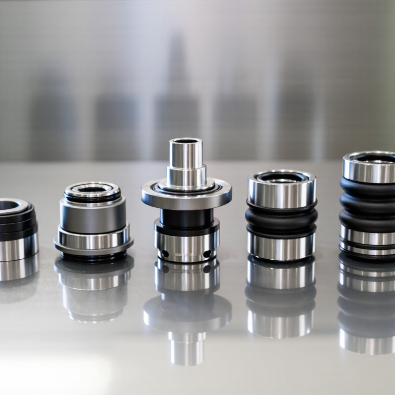
Mechanical shaft seals limit leakage where a rotating shaft passes through a stationary housing. A spring or other loading mechanism presses two flat faces together. One face rotates with the shaft; the other remains fixed. A very thin fluid film usually separates them, reducing friction while helping contain the process fluid. Too little lubrication can cause heat and wear. Too much leakage may signal damage or poor installation.
The “top 10” types are not one tidy, exclusive list. Seals are classified by different features, and categories can overlap. Common types include single, double, and tandem seals; balanced and unbalanced seals; pusher and metal-bellows seals; cartridge and component seals; split seals; and gas-lubricated seals. Single or double describes the arrangement. Balanced or unbalanced describes how pressure acts on the faces. Pusher and bellows designs differ in how they accommodate shaft movement. Cartridge seals arrive as a preassembled unit, while split seals can be fitted around some installed shafts. Gas-lubricated designs use a gas film instead of relying on liquid lubrication. No category alone guarantees suitability.
Tips: Check fluid properties, pressure, temperature, shaft speed, and alignment before choosing a seal. Look for dry running or uneven face wear during inspection. Even a well-selected seal can fail if installation is careless.
Mechanical shaft seals limit leakage where a rotating shaft enters a pump or other equipment. Conventional seals use separate rotating and stationary faces, springs, and elastomers. They work well in many standard installations. But fitting takes care. Face alignment, spring position, and clean surfaces all matter. A tiny grain of grit can score a sealing face.
Cartridge seals arrive assembled with key parts set in place. This reduces on-site measuring and can make installation more repeatable, especially when access is awkward. Split seals divide into sections around the shaft, so technicians may replace them without removing connected equipment. That can save substantial downtime. Still, split designs need precise assembly, and neither type suits every pressure, temperature, or fluid. Check the equipment’s operating limits before selecting a seal.
Tips: Confirm shaft size, operating conditions, and seal-face materials against equipment records. Keep faces clean during fitting. If leakage returns quickly, review alignment and operating conditions rather than assuming the seal alone is at fault.
Mechanical shaft seals are commonly grouped by how they handle wear and fluid pressure. Pusher designs use a sliding secondary seal, often an O-ring, that moves along the shaft as the seal faces wear. This helps maintain contact over time. But abrasive particles or deposits can restrict that movement. Small details matter.
Non-pusher seals use a flexible bellows to accommodate wear instead. The bellows may be metal or elastomer, so material choice must suit the fluid and temperature. With no sliding secondary seal on the shaft, some sticking problems are reduced. Movement is limited, though, and bellows can be sensitive to poor installation or excessive vibration.
Balanced and unbalanced designs describe a different feature: the hydraulic force pressing the seal faces together. A balanced seal reduces that closing force, often making it a better candidate for higher-pressure service or heat-sensitive fluids. An unbalanced seal is simpler and may work well at lower pressures, but rising pressure can increase face loading, friction, and heat. These categories can overlap: a seal may be both pusher and balanced. In practice, pressure is only part of the decision. Shaft runout, fluid cleanliness, temperature swings, and flush conditions can change how a design performs. Real installations are rarely as tidy as a selection chart suggests.
A single mechanical seal uses one sealing interface between the rotating shaft and stationary housing. It is compact and often suits clean, low-hazard fluids when leakage can be managed. API Standard 682 classifies this as Arrangement 1. Its simplicity helps maintenance, but a damaged seal can allow process fluid to escape directly. Small leaks still matter.
Double seals place two sealing interfaces around a buffer or barrier fluid. In an unpressurized arrangement, buffer fluid sits between the seals; in a pressurized arrangement, barrier fluid pressure exceeds process pressure. Tandem seals are a common unpressurized configuration, with both seals oriented in series and the outboard seal providing backup. API 682 distinguishes these arrangements because fluid pressure and circulation affect leakage direction and monitoring. The U.S. Department of Energy’s Improving Pumping System Performance guide estimates that pumping systems use nearly 20% of global electricity, a reminder that seal support and pump efficiency deserve joint attention. Field choices are rarely that tidy.
Tips: Check fluid compatibility, temperature, and pressure before choosing. For tandem service, monitor buffer-fluid level and leakage routinely. A clean drain pot helps reveal changes early. Still, the best arrangement depends on the actual process, not a rule of thumb.
Mechanical shaft seals are often grouped as pusher, non-pusher, balanced, unbalanced, cartridge, split, dry-running, metal-bellows, elastomer-bellows, and tandem or double seals. These labels overlap: a cartridge seal, for example, may also be balanced. The useful question is not which type ranks highest, but which design suits the actual service.
Start with the fluid, pressure, temperature, and shaft speed. Hot fluid can harden elastomers, while abrasive particles may score seal faces. High pressure can increase face loading, so a balanced design may help reduce friction and heat. Heat changes everything. For a pump handling a clean, cool liquid, a single seal may be practical. A hazardous or costly fluid may call for a double arrangement with a compatible barrier fluid. Dry-running designs can tolerate brief loss of lubrication, but they are not a cure for repeated operation without liquid.
Check the machine, too. Shaft runout, vibration, misalignment, and frequent starts can shorten seal life, even when the process data looks suitable. A split seal may simplify work on large equipment that cannot be easily dismantled. A cartridge can reduce installation errors, though correct piping and setup still matter. Small details matter. Confirm materials against the fluid’s chemistry, then review operating records and maintenance access. Field data helps, but no selection chart captures every transient condition. A measured trial may reveal what calculations miss.
„Thanks to the LUVIR technology, the solder resist process could be switched directly from the previously used mask exposure to direct exposure. As an outstanding digital solution on the market, this technology has been able to demonstrate fast process times and superior quality on our certified conventional ink in production. This allowed us to fully digitize the solder mask process at low cost – without process or ink adjustments. An excellent benefit to our production in Rot am See.“
Ralf Göhringer (Head of Production WE Rot am See)
I would definitely recommend the Limata machine and team for a future company purchase
Michael Greenaway
Compunetics Inc.
“The Limata ldi has been amazing!! Best thing we did was buy this machine”
Richard Brady
GM
Circuitlabs
“Since 2019, we have been running the Limata X1000 LDI system (including LUVIR for solder mask imaging) in daily production as an addition to our current process with film. The machine was capable of properly exposing Taiyo PSR-4000 BN (DI) solder mask types on normal to high-copper boards using a new and unique direct imaging process. The machine operating interface is very user friendly which allowed for a quick technical training curve. The pre-registration processing reduced several seconds of production time at every print. Limata support and service staff is incomparable. They supported our team every step of the way at basically any time of the day or night, with literally, an immediate response time, customizing the software interface to best fit our Operations and needs.
We have exposed more than 8,000 prints since end of October, on various solder mask colors and some resist film panels. Limata, has proven to be very capable and innovative. They are a strong contender in the industry.
We have very much enjoyed this project, and working with the team!
Thank you Limata for the continued support and being a part of our growth.”
Bill Sezate
Vice President, GM
Summit Interconnect
As a replacement to our current contact exposure process with film, the LIMATA X2000 system including LUVIR-Technology was capable of properly exposing non-LDI solder mask types using a direct imaging process. The machine offers cutting edge software with a very intuitive operating interface which allowed for quick technician training curve. The dual drawer system combined with pre-registration processing reduced several seconds of production time at every machine cycle. Limata support and service staff is world class. They added software patches to keep production running at shortest possible response times, customized the software interface to best fit our in-house Operations system, and even wrote a step-by-step machine processing manual. As a result of the project, we have exposed more than 16,000 times on various product types and solder mask brands/colors. Limata, in a very short timeframe as a company, has definitely shown they are truly innovative and will be challenging the industry of direct imaging for the top spot.
Kevin Beattie
Process Engineer
TTM Technologies
Forest Grove Division
