A Bending Machine can look similar in a catalog yet perform very differently on a production floor. Buyers must compare tonnage, bending length, repeatability, control systems, tooling availability, and local service—not price alone. The scale of industrial production makes these choices consequential. World Steel Association’s World Steel in Figures 2025 reports 1,882.6 million tonnes of crude steel production in 2024. That is useful context, not a direct measure of bending-machine demand.
Automation also shapes equipment decisions. The International Federation of Robotics’ World Robotics 2024 report recorded 541,302 industrial robot installations in 2023, with 4.28 million robots operating in factories worldwide. Those figures help explain interest in press brakes that can integrate with robotic handling and digital production systems. But automation is not automatically the right answer. A small fabrication shop may gain more from straightforward setup, dependable components, and accessible technical support.
This guide introduces manufacturers serving global buyers and considers practical differences between their machines, product ranges, and service networks. It also highlights details worth verifying: published accuracy conditions, controller compatibility, spare-parts lead times, and commissioning support. Ask for evidence. A specification sheet alone cannot show how a machine behaves with your material, tooling, and operators. Rankings can simplify research, but they are never a substitute for a trial or a careful supplier review.
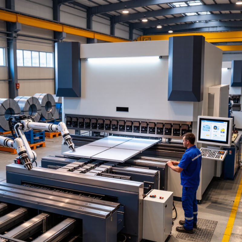
Bending machines should be classified by how they form the workpiece, not by capacity alone. Press brakes use a punch and die for straight bends; roll benders curve plate through rollers, while panel benders fold sheet along programmed edges. Each process needs different tooling and setup. The distinction matters on the shop floor.
Compare force in kilonewtons (kN) and working length in millimetres (mm). Press-brake force must account for material strength, thickness, bend length, and die opening. A 2,000 kN machine with a 3,000 mm bed is not automatically suitable for every 3,000 mm bend. Force charts are useful, but they rely on stated assumptions. Check the actual material grade and tooling; estimates can be optimistic.
For market context, Allied Market Research estimated the broader metal-forming machine-tools market at USD 41.2 billion in 2021, forecasting USD 62.6 billion by 2031. That figure covers more than bending machines, so it should not be read as a bending-machine sales estimate. When comparing suppliers, request rated force, usable working length, and force capacity across the bed. Also ask whether the frame and tooling support the intended load. A detail is easy to miss: long parts may deflect even when the nominal force looks sufficient. A practical test bend can reveal that.
| Machine Type | Bending Process | Typical Rated Force (kN) | Typical Working Length (mm) | Common Applications | Selection Notes |
|---|---|---|---|---|---|
| CNC hydraulic press brake | Hydraulic rams drive a punch into a die; CNC controls the stroke and backgauge for air bending, bottoming, or coining. | 400–3,000 | 1,250–6,000 | Sheet-metal enclosures, brackets, cabinets, and general fabrication. | A versatile option for varied materials and batch sizes. Required force depends on material strength, thickness, bend length, and die opening. |
| Servo-electric press brake | Electric servo motors and a drive mechanism move the ram; bending is typically performed with a punch and die. | 100–1,000 | 500–3,000 | Precision parts, electronics housings, and light- to medium-gauge sheet metal. | Often selected for short-cycle, repeatable work. Available force and working length vary by machine design. |
| Hybrid press brake | Servo-driven hydraulic pumps power hydraulic cylinders, combining hydraulic bending with demand-based pump control. | 300–3,000 | 1,250–6,000 | General-purpose production where both forming capacity and controlled energy use are priorities. | Compare rated force, speed, and control features across the full working range; “hybrid” configurations differ between machine designs. |
| Mechanical press brake | A motor-driven flywheel and mechanical linkage deliver ram movement for punch-and-die bending. | 100–2,000 | 1,000–4,000 | Repetitive bending jobs using established tooling and production setups. | Check stroke, shut height, and forming capacity at the intended working position, as these affect practical job suitability. |
| Tandem press-brake system | Two synchronized press brakes bend long workpieces together; each machine has its own ram and tooling. | 2,000–12,000 combined (typically 2 × 1,000–6,000) | 4,000–16,000 combined | Long panels, structural components, and other workpieces that exceed a single machine’s bed length. | Confirm synchronization, combined force, tooling alignment, and usable length for the specific paired-machine configuration. |
| Heavy-duty hydraulic press brake | High-force hydraulic ram bends thick plate or long sections using matched punches and dies. | 3,000–30,000 | 4,000–14,000 | Heavy fabrication, industrial equipment, structural parts, and thick-plate forming. | These are broad ranges for large-capacity configurations. Verify force requirements against material grade, thickness, bend length, and tooling. |
Note: Capacity ranges are indicative examples, not standardized limits or a specification for any particular machine. Rated force and working length vary by configuration. Confirm the required bending force using the material, thickness, bend length, tooling, and bending method for the intended job.
Global bending machine manufacturers differ in frame design, control software, automation options, and service coverage. For high-mix work, prioritize quick setup, clear programming, and easy tool changes. For long production runs, repeatability and automated part handling may matter more. Compare the machines using your own drawings, material grades, thicknesses, and bend sequences—not only sample parts prepared for a showroom.
Check how each supplier supports installation, operator training, spare parts, and remote troubleshooting in your region. Ask for a trial using a challenging part, such as a narrow flange in stainless steel. Watch for angle variation, handling difficulty, and setup time. A polished demonstration can hide a steep learning curve. That deserves a closer look.
Tips: Bring real production data to supplier meetings. Request cycle-time estimates and clarify what they exclude. Check service response expectations in writing, and ask operators to test the interface. A small setup detail can become a daily frustration.
For a CNC press brake, axis positioning accuracy affects where the ram and backgauge actually stop. ISO 230-2:2014 provides methods for testing the positioning accuracy and repeatability of numerically controlled axes. A buyer can ask for results on relevant axes, such as Y1, Y2, and X, across several points of travel. Small errors matter. The report should state the test conditions, measurement method, and approach direction, since readings can differ when an axis moves from opposite directions.
A repeatability figure alone does not show how close an axis gets to its commanded position. Ask for unidirectional and bidirectional results, and check whether the test points cover the machine’s usable travel. A calibrated laser interferometer is one possible measurement tool. Temperature and machine setup matter, too; a polished report from a stabilized workshop may not mirror a busy production floor. That is useful. Compare suppliers using similar test conditions, and treat ISO axis results as one part of evaluation. They do not, by themselves, prove that every bend will meet a target angle under load. Requesting the actual test record, rather than a single accuracy claim, gives a clearer basis for comparing machines.
When comparing press-brake suppliers, ask how they identify the machine’s safety standard and document their assessment. ISO 16092-2:2019 addresses mechanical presses, so buyers should confirm that it applies to the specific machine design. A press brake may require additional, machine-specific references. A standards checklist alone is not proof of safe operation.
Look for practical evidence: documented risk assessment, clear operating instructions, and verified protective devices. Depending on the machine and task, checks may cover guards, light curtains, two-hand controls, foot controls, and safe setup modes. Ask how stopping performance was measured and whether the protective distance matches the installed configuration. A brochure is not enough. Request records from commissioning and ask who is responsible for periodic checks.
Watch a real bending cycle, not just a demonstration with no material. Observe the operator’s hands, the tool area, and how the machine behaves during setup and faults. Even a well-maintained safeguard can be poorly positioned after a changeover. One uncomfortable question is easy to miss: can the operator bypass protection during routine work? Treat vague answers as a reason to investigate further, and have a competent safety professional confirm standard applicability and machine-specific requirements.
When comparing bending machine suppliers, rated tonnage is only a starting point. Match the machine’s capacity to your material, thickness, bend length, and tooling. A high tonnage figure may not guarantee consistent bends across a long workpiece. Ask for the working force chart and confirm how capacity changes with material type and bend width. Request a test using a sample part close to your own.
Bending length matters too. Measure your largest planned component, then check the usable distance between the machine’s side frames. Small differences can affect setup and part handling. Service deserves equal attention. Ask who handles installation, operator training, spare parts, and urgent troubleshooting. A clear response-time commitment is more useful than a vague promise of support. Very useful. Lead time should include production, inspection, shipping, and commissioning—not just factory completion. Get each stage in writing, and ask what could delay it. A specification sheet can still mislead. Compare the details, then verify the claims with drawings, test records, and references for similar applications.
Compare press brake capacity and the supplier details to verify before purchasing.
The chart shows example press brake capacity configurations, not verified specifications from particular manufacturers or a market survey. Actual tonnage and bending length depend on the machine model and setup. Compare supplier quotations for confirmed capacity, service coverage, and delivery lead time.
„Thanks to the LUVIR technology, the solder resist process could be switched directly from the previously used mask exposure to direct exposure. As an outstanding digital solution on the market, this technology has been able to demonstrate fast process times and superior quality on our certified conventional ink in production. This allowed us to fully digitize the solder mask process at low cost – without process or ink adjustments. An excellent benefit to our production in Rot am See.“
Ralf Göhringer (Head of Production WE Rot am See)
I would definitely recommend the Limata machine and team for a future company purchase
Michael Greenaway
Compunetics Inc.
“The Limata ldi has been amazing!! Best thing we did was buy this machine”
Richard Brady
GM
Circuitlabs
“Since 2019, we have been running the Limata X1000 LDI system (including LUVIR for solder mask imaging) in daily production as an addition to our current process with film. The machine was capable of properly exposing Taiyo PSR-4000 BN (DI) solder mask types on normal to high-copper boards using a new and unique direct imaging process. The machine operating interface is very user friendly which allowed for a quick technical training curve. The pre-registration processing reduced several seconds of production time at every print. Limata support and service staff is incomparable. They supported our team every step of the way at basically any time of the day or night, with literally, an immediate response time, customizing the software interface to best fit our Operations and needs.
We have exposed more than 8,000 prints since end of October, on various solder mask colors and some resist film panels. Limata, has proven to be very capable and innovative. They are a strong contender in the industry.
We have very much enjoyed this project, and working with the team!
Thank you Limata for the continued support and being a part of our growth.”
Bill Sezate
Vice President, GM
Summit Interconnect
As a replacement to our current contact exposure process with film, the LIMATA X2000 system including LUVIR-Technology was capable of properly exposing non-LDI solder mask types using a direct imaging process. The machine offers cutting edge software with a very intuitive operating interface which allowed for quick technician training curve. The dual drawer system combined with pre-registration processing reduced several seconds of production time at every machine cycle. Limata support and service staff is world class. They added software patches to keep production running at shortest possible response times, customized the software interface to best fit our in-house Operations system, and even wrote a step-by-step machine processing manual. As a result of the project, we have exposed more than 16,000 times on various product types and solder mask brands/colors. Limata, in a very short timeframe as a company, has definitely shown they are truly innovative and will be challenging the industry of direct imaging for the top spot.
Kevin Beattie
Process Engineer
TTM Technologies
Forest Grove Division
