Choosing a Digital Signal Isolator is rarely a simple parts-list exercise. The right device must match the signal, system voltage, board space, and operating environment. A small mismatch can affect timing, noise immunity, or integration work.
Global buyers also compare practical details. These include channel count, data rate, isolation rating, common-mode transient immunity, package options, and temperature range. Supply requirements matter too. A design using a 3.3-volt controller may need different interface planning than one built around 5-volt logic. Availability, clear datasheets, and responsive technical support can shape a purchase just as much as headline specifications. That matters.
This guide reviews ten digital signal isolators for buyers comparing options across markets and applications. It highlights the specifications that help narrow a shortlist, while recognizing that product pages cannot answer every engineering question. Bench testing may still be needed, especially when signals switch quickly or board layouts are crowded. Some figures look tidy on paper. Real circuits are less tidy.
No single ranking can fit every project. A low-power device may suit a compact instrument, while a multichannel part may better serve industrial control equipment. Buyers should check current manufacturer documentation and confirm that listed limits match their own design conditions. The comparison is a starting point, not a substitute for careful validation. Even experienced teams can overlook a small interface detail. One missed assumption can mean another board revision.
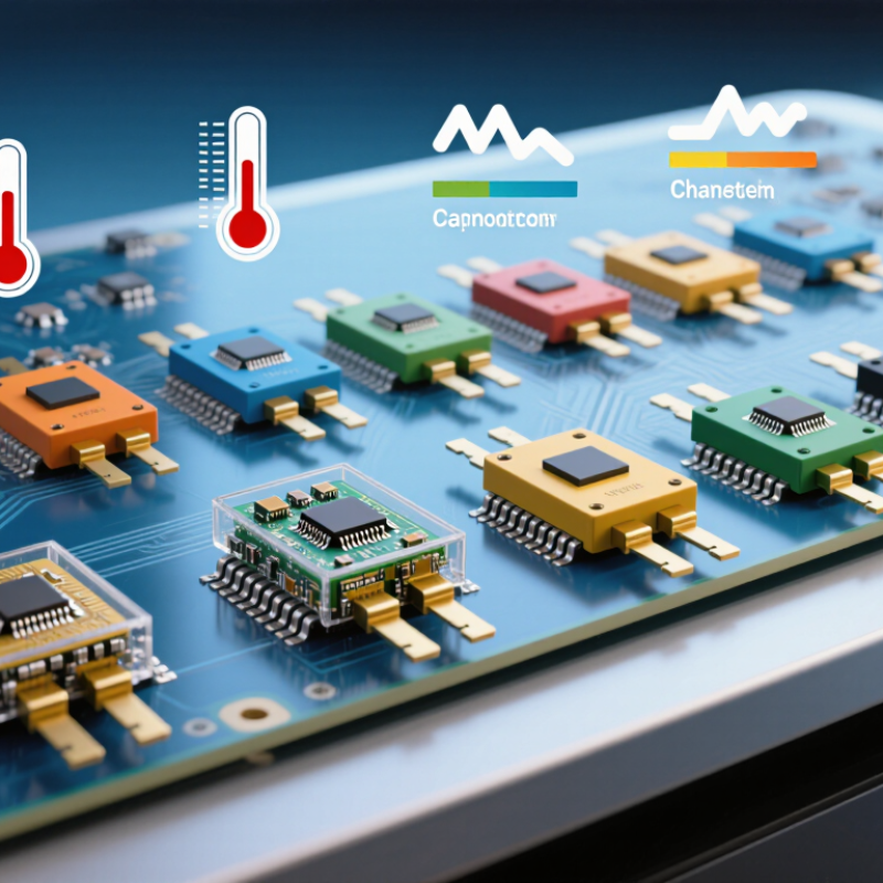
A digital signal isolator carries logic across a galvanic barrier without a conductive connection. On one side, an input circuit converts a digital edge into a changing electric or magnetic field. Capacitive designs use tiny coupling plates; magnetic designs use coils. A receiver detects the encoded change and rebuilds the logic pulse on the other side. No metal bridge. Each side typically needs its own power supply.
The key specifications describe different risks. Isolation voltage concerns electrical separation; propagation delay and data rate affect timing; common-mode transient immunity indicates resistance to fast voltage shifts. IEC 60747-17:2020 covers magnetic and capacitive couplers and their insulation test methods. But a standard test result does not replace checking the isolator’s working voltage, board spacing, and operating conditions.
System context matters, too. IEEE 802.3cg-2019 specifies 10 Mb/s single-pair Ethernet over distances up to 1 km. That figure describes a network link, not an isolator’s guaranteed performance. The isolator must still preserve pulse timing and tolerate noise at the interface. Isolation is not immunity. In practice, layout parasitics, supply noise, and temperature can complicate a clean datasheet comparison; I would verify them in the intended circuit.
A digital signal isolator transfers logic-state information across an insulation barrier without a direct conductive path. Capacitive or magnetic coupling conveys the signal, and the output reproduces its state after a propagation delay. This illustrative waveform uses 0–3.3 V logic levels and a 20 ns delay; actual values vary by device and operating conditions.
Digital signal isolators should be compared by the job they must perform, not by one headline number. Check channel count and direction first. A four-channel part may not suit a design needing three forward channels and one return channel. Then compare maximum data rate with the signal’s actual timing needs. Propagation delay and pulse-width distortion matter in tightly timed control loops.
Isolation ratings need careful reading. Withstand voltage describes a test condition, while working voltage relates to continuous operation. They are not interchangeable. Review creepage and clearance, package dimensions, operating temperature, and common-mode transient immunity (CMTI). A high CMTI rating can help when fast voltage changes occur nearby. Also verify supply voltage and logic-level compatibility; small mismatches can cause unreliable switching.
Tips: Compare values under the same test conditions. Check the datasheet footnotes, not just the summary table. A neat table can still hide a mismatch. For a shortlist, record each candidate’s channel layout, data rate, delay, isolation ratings, CMTI, and temperature range. Then check the actual board layout and expected noise environment. This step is easy to rush, and real installations may differ from bench tests.
Global buyers comparing the top 10 digital signal isolators should look beyond channel count and headline isolation voltage. The Semiconductor Industry Association reported global semiconductor sales of $627.6 billion in 2024, reflecting a vast, internationally connected supply chain. That figure is not isolator-specific, but it underscores why buyers should check production continuity and documentation. A shortlist should include working voltage, transient immunity, common-mode transient immunity (CMTI), propagation delay, and isolation capacitance. Small differences matter. For example, high CMTI can help preserve signal integrity near fast-switching power stages.
Compare datasheets under the same test conditions. Check creepage and clearance against the intended board layout, then confirm the package, temperature range, and channel direction suit the design. IEC 60747-17:2020 covers magnetic and capacitive couplers; it offers a useful reference when reviewing component safety data. Ask suppliers for test methods, qualification details, and change-notification policies. Datasheets may not answer every application question, so validate shortlisted parts on the actual board.
Tips: Measure the isolator’s timing and noise performance in your circuit. Keep a record of test conditions. A tidy table helps, though it cannot replace bench testing.
Global Certifications, Availability, and Supply Considerations
For global buyers, a digital signal isolator is only as dependable as its verified documentation. Ask suppliers for current declarations and safety approvals tied to the exact part number, package, and manufacturing site. Common references may include UL 1577 and relevant IEC or VDE standards, but coverage varies by device and revision. Do not assume a family-level certificate covers every variant. Check isolation voltage, working voltage, creepage, clearance, and test conditions against the end equipment’s requirements. Paperwork matters. A certificate is not a design review.
Availability needs the same scrutiny. Request lead-time ranges, authorized-channel status, date-code expectations, and notice of product changes or end-of-life plans. Stock can shift. An “in stock” listing may represent one small reel, not ongoing production. For products shipping across regions, compare approved alternatives before layout freeze. Confirm pin compatibility, timing limits, package dimensions, and certification status. Allow time for qualification and logistics; regional inventory and customs documentation can add delays. A small suffix mismatch can consume weeks of qualification time. It is unglamorous, but worth checking early.
Selecting a digital signal isolator starts with the signals it must carry. Count the channels, note their direction, and record the required data rate. For SPI, check clock speed and propagation delay; for a fault-monitoring input, timing may be less demanding. Faster is not always better. Higher data rates can increase power use and narrow design margins.
Compare the isolation rating with the actual working voltage and transient conditions in your equipment. Check common-mode transient immunity, temperature range, package size, and whether the output defaults safely when the input is absent. Board layout matters too: creepage and clearance depend on the package and the surrounding design, not just the component listing.
A useful bench check is to measure signal timing and supply current under realistic loads. Datasheets help, but they cannot show every noise path on your board. I would revisit the choice after testing, especially if switching noise or cable length changes. No single specification settles the decision; weigh safety, timing, power, and layout together.
„Thanks to the LUVIR technology, the solder resist process could be switched directly from the previously used mask exposure to direct exposure. As an outstanding digital solution on the market, this technology has been able to demonstrate fast process times and superior quality on our certified conventional ink in production. This allowed us to fully digitize the solder mask process at low cost – without process or ink adjustments. An excellent benefit to our production in Rot am See.“
Ralf Göhringer (Head of Production WE Rot am See)
I would definitely recommend the Limata machine and team for a future company purchase
Michael Greenaway
Compunetics Inc.
“The Limata ldi has been amazing!! Best thing we did was buy this machine”
Richard Brady
GM
Circuitlabs
“Since 2019, we have been running the Limata X1000 LDI system (including LUVIR for solder mask imaging) in daily production as an addition to our current process with film. The machine was capable of properly exposing Taiyo PSR-4000 BN (DI) solder mask types on normal to high-copper boards using a new and unique direct imaging process. The machine operating interface is very user friendly which allowed for a quick technical training curve. The pre-registration processing reduced several seconds of production time at every print. Limata support and service staff is incomparable. They supported our team every step of the way at basically any time of the day or night, with literally, an immediate response time, customizing the software interface to best fit our Operations and needs.
We have exposed more than 8,000 prints since end of October, on various solder mask colors and some resist film panels. Limata, has proven to be very capable and innovative. They are a strong contender in the industry.
We have very much enjoyed this project, and working with the team!
Thank you Limata for the continued support and being a part of our growth.”
Bill Sezate
Vice President, GM
Summit Interconnect
As a replacement to our current contact exposure process with film, the LIMATA X2000 system including LUVIR-Technology was capable of properly exposing non-LDI solder mask types using a direct imaging process. The machine offers cutting edge software with a very intuitive operating interface which allowed for quick technician training curve. The dual drawer system combined with pre-registration processing reduced several seconds of production time at every machine cycle. Limata support and service staff is world class. They added software patches to keep production running at shortest possible response times, customized the software interface to best fit our in-house Operations system, and even wrote a step-by-step machine processing manual. As a result of the project, we have exposed more than 16,000 times on various product types and solder mask brands/colors. Limata, in a very short timeframe as a company, has definitely shown they are truly innovative and will be challenging the industry of direct imaging for the top spot.
Kevin Beattie
Process Engineer
TTM Technologies
Forest Grove Division
