Industrial Power Supply manufacturers sit behind the machines that keep factories, data centers, and process lines running. Their products convert and regulate power, often inside hot cabinets, beside vibrating motors, and under continuous load. Small design differences matter. A stable output can protect control systems; poor thermal design may shorten service life.
The International Energy Agency’s Electricity 2024 report projects global electricity demand will grow by an average of 3.4% annually through 2026. That broader trend raises the stakes for efficient, dependable power conversion. IEA Executive Director Fatih Birol has described the wider shift as the “Age of Electricity.” It is a useful lens, though not a direct forecast for industrial power supply sales. Market boundaries differ, too. Some reports group industrial units with broader power-conversion products, so headline market figures need careful reading.
This guide compares leading manufacturers through practical criteria: output range, efficiency, protection features, certifications, customization, and regional service. A datasheet can look convincing. The harder test is performance after years of heat, dust, and load changes. No ranking can replace application-specific engineering review. That caveat matters. Readers should verify current specifications and support terms before selecting a supplier, especially for critical equipment. The strongest manufacturers combine proven product design with clear documentation and responsive technical support. Still, even reputable brands can be a poor fit when voltage, mounting, or environmental requirements are overlooked.
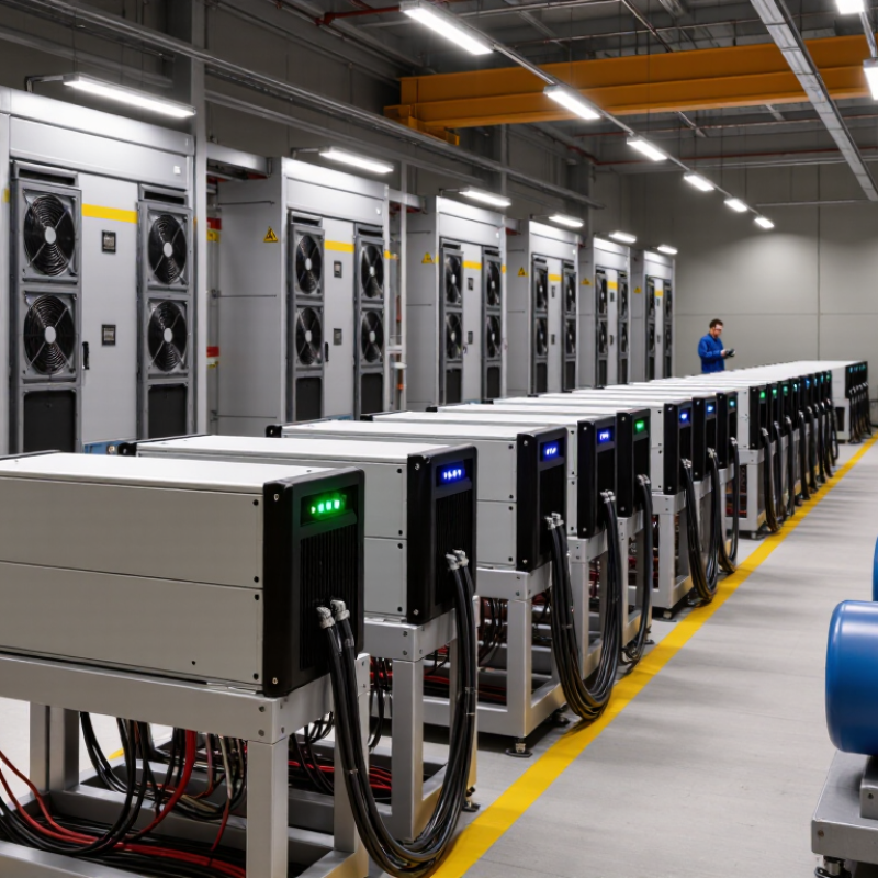
Industrial power supplies convert incoming AC into regulated DC for control panels, sensors, relays, and other equipment. Inside the unit, rectification and switching circuits transform the input, while regulation keeps the output within specified limits. A 24 VDC output is common because it suits many industrial control devices and simplifies wiring across a panel. It is not universal.
A label marked 24 V does not tell the whole story. Engineers also check available current, ripple, overload behavior, and the permitted input range. For example, a supply feeding a controller and several valves must handle their combined demand, including brief startup surges. Leave practical headroom. Then check the equipment manuals and the supply’s datasheet; ratings can vary with temperature and installation conditions. Hot enclosures matter.
Mounting and wiring affect real-world performance, too. Keep ventilation openings clear, secure conductors in the terminals, and separate power wiring from sensitive signal cables where practical. Measure the output under load, not only with disconnected equipment. A meter reading can look fine at idle. One detail is easy to miss: long cable runs can cause voltage drop at the device. I would recheck that at the far end, especially when loads switch on. Manufacturers publish specifications, but the panel’s actual heat, wiring, and load pattern still deserve attention.
| Comparison Dimension | Typical Industrial Power Supply Information | Practical Significance |
|---|---|---|
| Conversion function | Converts alternating-current (AC) input into regulated direct-current (DC) output. | Provides a DC supply for control equipment and other loads in industrial systems. |
| Common DC output | 24 VDC is widely used in industrial control systems. | Commonly supplies devices such as sensors, relays, controllers, and other 24 V equipment; compatibility must be checked for each load. |
| AC input voltage | Many models are designed for nominal 100–240 VAC input. Some specify an operating range such as 85–264 VAC. | Input limits and permitted frequency vary by model. Confirm the product rating against the site’s supply voltage. |
| Input frequency | 50/60 Hz is a common mains-frequency specification. | Check the nameplate or datasheet, especially for installations with non-standard power sources. |
| 60 W output class | At 24 VDC: 2.5 A maximum nominal output current (60 W ÷ 24 V). | Suitable only when the connected load’s continuous and peak demand fit within the supply’s ratings. |
| 120 W output class | At 24 VDC: 5 A maximum nominal output current (120 W ÷ 24 V). | Allow for load variation, startup current, and any required engineering margin. |
| 240 W output class | At 24 VDC: 10 A maximum nominal output current (240 W ÷ 24 V). | Check wiring, terminal ratings, ambient temperature, and mounting conditions at the intended current. |
| 480 W output class | At 24 VDC: 20 A maximum nominal output current (480 W ÷ 24 V). | Higher-current installations may need careful conductor sizing and distribution planning. |
| Output-current calculation | Current (A) = output power (W) ÷ output voltage (V). | For a 24 V output, a 240 W supply has a nominal rated current of 10 A. |
| Common protection features | Overload, overvoltage, and short-circuit protection are commonly offered, but features and behavior differ by model. | Review the datasheet to confirm protection thresholds, recovery behavior, and any required system-level protection. |
| Efficiency and heat | Efficiency is model- and load-dependent; the manufacturer’s datasheet gives the rated values and test conditions. | Efficiency affects input power, heat dissipation, and enclosure thermal design. |
| Installation and environment | DIN-rail and panel-mount formats are common. Permitted ambient temperature and derating vary by product. | Verify mounting method, ventilation, temperature limits, and derating before installation. |
Note: Output-current figures above are calculated from the stated power and 24 V output. Input ranges, protections, efficiency, and environmental ratings are product-specific; consult the relevant datasheet before selection or installation.
Industrial power supply manufacturers serve different needs, even when their products share familiar voltage ratings. Some focus on compact, cost-conscious units for control panels; others offer broad portfolios, rugged construction, or configurable systems. Compare the actual operating range, not just the headline specifications.
A useful review starts with load behavior. Check startup current, peak demand, ripple tolerance, and expected ambient temperature. Then inspect derating curves, short-circuit response, and protection features. In a cabinet, a few degrees of extra heat can matter. So can a loose terminal. Bench tests help, but evaluate the supply alongside the equipment it will run. The difference is real.
Worldwide suppliers vary in regional support, documentation quality, lead times, and product longevity. Ask for lifecycle notices and application guidance, especially when equipment must operate for years. Review independent test records and relevant safety approvals for the intended market. A polished datasheet is useful, but it cannot predict every installation. I still leave room for uncertainty: wiring habits and ventilation are often less controlled than design plans suggest.
Industrial power supplies should be chosen for their installation conditions, not wattage alone. DIN-rail units clip onto control-cabinet rails and suit PLCs, sensors, and compact machine controls. Enclosed supplies protect internal components, but their ventilation and ingress ratings still matter. Open-frame designs fit tightly inside larger equipment; exposed circuitry needs guarded mounting. Modular supplies allow engineers to add or replace output modules as loads change. Flexibility helps. Yet it can complicate sizing.
The International Federation of Robotics’ World Robotics 2024 report recorded 4,281,585 industrial robots operating worldwide in 2023, a 10% increase from 2022. This expanding automation footprint highlights the need for dependable power in production systems, though it does not predict demand for any specific supply type. Compare output voltage, peak load, operating temperature, and expected service access. A supply that fits today’s cabinet may become awkward after a control upgrade.
Tips: Check the heat. Measure cabinet clearance and airflow at full load, then verify derating against the manufacturer’s datasheet. For open-frame units, plan touch protection and mounting space before assembly. For modular systems, confirm that replacement modules match the required output and load profile. Don’t size by watts alone.
Industrial power supplies should be compared by more than their headline wattage. Output voltage must match the load, while acceptable tolerance and ripple depend on the equipment being powered. Rated power describes the unit’s specified capacity under stated conditions, not necessarily its capacity inside a hot, crowded enclosure. Efficiency matters too: at 90 percent efficiency, a 240-watt output requires more input power, and the difference becomes heat. Small details add up.
For a 24-volt load drawing 8 amps, the required output is 192 watts. A 240-watt supply appears to provide a useful margin, but ambient temperature, installation orientation, and airflow can reduce its available power. Check the manufacturer’s thermal derating curve at the expected cabinet temperature. Heat changes the answer. A tidy specification table cannot replace a realistic assessment of wiring, ventilation, and peak demand; those conditions are easy to underestimate.
Tips: Compare voltage tolerance, rated power, efficiency at your typical load, and derating data side by side. Check whether the stated rating assumes free airflow or a specific mounting position. Leave practical headroom for startup surges and temperature changes, then verify the choice under representative operating conditions. One uncomfortable question remains: will the cabinet still run cool after years of dust and routine maintenance?
For industrial power supply manufacturers, IEC 61000-3-2 sets a clear EMC boundary: it covers equipment drawing up to and including 16 A per phase from public low-voltage systems. The IEC 61000-3-2:2018 edition and its amendments define harmonic-current limits by equipment class. This matters because a compact DIN-rail supply and a larger cabinet unit may face different test conditions, even when their power ratings appear similar. The 16 A figure is a scope threshold, not a compliance result.
Harmonic testing measures current components at multiples of the supply frequency. A distorted waveform can affect nearby equipment and complicate system-level performance. Designers should check the correct equipment class, input voltage, and operating mode before testing. A common trap is treating a passing result at one load as proof for every configuration. It is not. Records should link the tested sample to its circuit design and production controls.
Tips: Verify the phase-current rating and intended connection type early. Test realistic load conditions, including low-load operation. Keep the test report and configuration details together; small changes to input filtering can alter harmonic results.
„Thanks to the LUVIR technology, the solder resist process could be switched directly from the previously used mask exposure to direct exposure. As an outstanding digital solution on the market, this technology has been able to demonstrate fast process times and superior quality on our certified conventional ink in production. This allowed us to fully digitize the solder mask process at low cost – without process or ink adjustments. An excellent benefit to our production in Rot am See.“
Ralf Göhringer (Head of Production WE Rot am See)
I would definitely recommend the Limata machine and team for a future company purchase
Michael Greenaway
Compunetics Inc.
“The Limata ldi has been amazing!! Best thing we did was buy this machine”
Richard Brady
GM
Circuitlabs
“Since 2019, we have been running the Limata X1000 LDI system (including LUVIR for solder mask imaging) in daily production as an addition to our current process with film. The machine was capable of properly exposing Taiyo PSR-4000 BN (DI) solder mask types on normal to high-copper boards using a new and unique direct imaging process. The machine operating interface is very user friendly which allowed for a quick technical training curve. The pre-registration processing reduced several seconds of production time at every print. Limata support and service staff is incomparable. They supported our team every step of the way at basically any time of the day or night, with literally, an immediate response time, customizing the software interface to best fit our Operations and needs.
We have exposed more than 8,000 prints since end of October, on various solder mask colors and some resist film panels. Limata, has proven to be very capable and innovative. They are a strong contender in the industry.
We have very much enjoyed this project, and working with the team!
Thank you Limata for the continued support and being a part of our growth.”
Bill Sezate
Vice President, GM
Summit Interconnect
As a replacement to our current contact exposure process with film, the LIMATA X2000 system including LUVIR-Technology was capable of properly exposing non-LDI solder mask types using a direct imaging process. The machine offers cutting edge software with a very intuitive operating interface which allowed for quick technician training curve. The dual drawer system combined with pre-registration processing reduced several seconds of production time at every machine cycle. Limata support and service staff is world class. They added software patches to keep production running at shortest possible response times, customized the software interface to best fit our in-house Operations system, and even wrote a step-by-step machine processing manual. As a result of the project, we have exposed more than 16,000 times on various product types and solder mask brands/colors. Limata, in a very short timeframe as a company, has definitely shown they are truly innovative and will be challenging the industry of direct imaging for the top spot.
Kevin Beattie
Process Engineer
TTM Technologies
Forest Grove Division