Understanding substation voltage levels starts with a practical question: how much power must move, and how far? Distribution substations commonly step voltage down for local networks, while transmission substations connect higher-voltage corridors. Typical AC examples include 11–33 kV distribution, 66–132 kV sub-transmission, and 220–400 kV transmission. Some systems also use 500 kV or 765 kV equipment. These ranges are illustrative, not universal. Regional grid design, equipment standards, and utility practice all matter.
The scale of grid investment makes the subject timely. The International Energy Agency’s 2023 report, Electricity Grids and Secure Energy Transitions, says more than 80 million kilometres of grids must be added or refurbished by 2040—roughly the length of today’s global grid. That figure signals major infrastructure needs, but it does not prescribe one ideal substation voltage. Higher voltages can move large amounts of power over long distances, yet insulation, clearances, switching equipment, and protection systems become more demanding. Details matter.
This overview compares common substation voltage classes, explains where they are used, and clarifies why “top” does not mean “best” in every network. AC and HVDC facilities also use different voltage conventions, so direct comparisons can mislead. The categories look neat on paper. Real grids are messier. IEEE and IEC standards help define equipment requirements, while project-specific studies determine suitable ratings. Even familiar voltage labels deserve a second look.
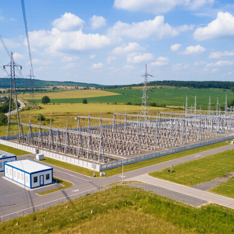
A substation’s voltage level is the nominal voltage of its busbars and connected equipment—not simply the largest number on its sign. It reflects the power system’s needs at that point: how much electricity must pass through, how far it travels, and which neighboring circuits it connects. Higher voltage generally moves bulk power with lower current for the same power, reducing resistive losses. But higher voltage also demands greater insulation distances, larger clearances, and suitably rated breakers and transformers.
The U.S. Energy Information Administration describes transmission voltages commonly ranging from 138 kV to 765 kV. This range helps explain why a substation may contain several voltage levels. Picture a 230/115-kV transformer beside two sets of busbars: one side links to a higher-voltage transmission corridor, while the other feeds a lower-voltage network. The transformer ratio alone does not define the entire station; the connected system and equipment ratings matter too. The U.S. Department of Energy’s 2023 National Transmission Needs Study estimates interregional transfer capacity needs to rise 20% by 2030 and 57% by 2040, relative to 2020 levels. That growth may influence future planning, but it does not automatically dictate a higher voltage at every substation. A tidy label can hide messy local constraints. Engineers must check load forecasts, fault levels, insulation coordination, and existing connections before choosing a nominal level.
Representative nominal AC voltage levels used in power systems worldwide
A substation’s voltage level is defined by the nominal voltage of the circuits and buses it serves. A single substation may handle multiple voltage levels, connected by transformers. These values are representative rather than universal; standards and operating voltages vary by region, and some grids also use levels such as 765 kV.
Common substation voltage levels depend on the power network, not one universal standard. Local utilities choose levels to match demand, distance, and existing equipment. Distribution substations often handle 4 to 35 kilovolts, including 11, 13.8, 22, and 33 kV. Some networks use 34.5 kV.
Subtransmission and transmission substations commonly operate at 69, 115, 138, 161, or 230 kV. Larger transmission systems may use 345, 500, or 765 kV. In many countries, 220, 275, and 400 kV are also familiar levels. The list can feel untidy. Neighboring regions may use different standards, even when their grids serve similar loads.
A transformer connects voltage levels, such as 115 kV and 13.8 kV, while switchgear and buswork must be rated for the system. On a substation drawing, the nominal voltage usually appears beside each bus. That number does not describe every operating condition: insulation clearances and equipment ratings account for surges and variation. A practical selection also considers future load growth and available fault capacity. These details matter. The highest voltage is not automatically the best choice; longer transmission distances may justify it, while local constraints can make a lower level more suitable.
What Are the Top Substation Voltage Levels?
How Voltage Levels Shape Substation Equipment
A substation’s voltage level influences nearly every major equipment choice. At higher voltages, transformers need stronger insulation, while switchgear requires greater electrical clearances. A 230-kilovolt yard, for example, usually needs more space between energized conductors than a compact medium-voltage installation. That extra distance affects busbar layout, supports, fencing, and maintenance access.
Circuit breakers, disconnect switches, instrument transformers, and surge arresters must all match the system’s operating voltage and expected fault conditions. Insulation coordination matters: engineers assess switching surges and lightning exposure when selecting protective equipment. Even small details count. Cable terminations need suitable insulation, and control systems must receive accurate signals from current and voltage transformers.
Higher voltage does not automatically mean better equipment or a better design. Site conditions, load patterns, reliability targets, and local engineering standards shape the final specification. A coastal site may need different corrosion protection than an inland yard. Real sites are less tidy than design tables suggest. Equipment clearances can look sufficient on paper, yet access roads, drainage, or future expansion may complicate the layout. Careful coordination across electrical and civil teams helps prevent those costly surprises.
Common nominal voltage levels and typical substation applications are shown below. Actual grid voltages, equipment ratings, and configurations vary by country, utility, and system design.
| Nominal Voltage Level | Typical Grid Role | How It Shapes Substation Equipment | Common Equipment Considerations |
|---|---|---|---|
| 11–15 kV | Local medium-voltage distribution to neighborhoods, commercial areas, and industrial customers. | Compact indoor or outdoor substations are common, with distribution transformers stepping voltage down for local use. | Metal-enclosed switchgear, circuit breakers, protection relays, and distribution transformers are typical. Insulation and clearances are lower than at transmission voltages. |
| 22–35 kV | Primary distribution and sub-transmission; often supplies large customers or feeds lower-voltage distribution networks. | Equipment is generally larger than at 11–15 kV, while many installations can still use compact switchgear arrangements. | Load-break switches or circuit breakers, instrument transformers, surge arresters, and step-down transformers are selected for the system’s rated voltage and fault level. |
| 66–69 kV | Sub-transmission and regional supply, particularly in networks that use this level to connect distribution areas. | Outdoor air-insulated layouts are common; some sites use gas-insulated equipment where space is limited. | Greater phase-to-phase and phase-to-ground clearances are needed than at distribution voltages. Busbars, breakers, disconnectors, and protection systems are sized for network conditions. |
| 110–138 kV | Sub-transmission and transmission connections between regional substations and load centers. | Substations typically require larger yards or more compact high-voltage switchgear, plus power transformers for voltage conversion. | High-voltage circuit breakers, disconnectors, instrument transformers, surge arresters, and coordinated insulation design are important. |
| 220–230 kV | Bulk transmission between major generation, transmission, and load-center substations. | Higher insulation levels and longer electrical clearances influence the size and layout of outdoor yards; bus arrangements are designed for reliability and maintenance. | High-capacity breakers, busbars, current and voltage transformers, protection relays, and transformer bays are typical. Switching overvoltages and lightning protection must be considered. |
| 345–400 kV | High-capacity transmission across regions and between major grid nodes. | Equipment spacing, insulation coordination, and substation footprint increase. Gas-insulated substations may be used where land is constrained. | Extra-high-voltage breakers, disconnectors, instrument transformers, surge arresters, and carefully designed grounding systems are required. |
| 500–765 kV | Long-distance, high-capacity transmission on some large interconnected grids. | Very large clearances and specialized insulation and switching design shape the substation layout. These installations are less common and typically serve major transmission corridors. | Equipment must address high electrical stresses, switching transients, and corona effects. Shunt reactors or other reactive-power equipment may be used to help manage voltage on long lines. |
Voltage categories are indicative rather than universal. The exact equipment rating is chosen to meet applicable standards, maximum system voltage, insulation requirements, fault current, and operating conditions.
Substation voltage levels differ because power systems grew under different historical, geographic, and economic conditions. A region may have built its first major grid around one transmission voltage, then expanded from that foundation. Existing transformers, switchgear, and protection settings make changing course costly. The old choice stays influential.
Geography matters, too. Long distances between power plants and cities can favor higher transmission voltages, which reduce current and line losses for a given amount of power. Dense urban networks may rely on different voltage steps to deliver electricity through crowded corridors. At a substation, a transformer’s nameplate shows the specific voltages it connects. Those ratings reflect local grid design, not a universal ranking.
Standards also depend on when and how networks connect. Neighboring regions may use different voltage levels because their systems developed separately, even when they now exchange electricity. Interconnection then requires compatible equipment, careful protection coordination, and clear operating procedures. Details matter. A voltage that works well on a long rural line may not suit a compact city network. It is tempting to call one standard more advanced, but that misses the practical trade-offs. I would treat voltage comparisons cautiously; the number alone says little about reliability or suitability.
Utilities choose a substation’s voltage level by matching the network’s needs, not by picking the largest available number. A distribution substation may step transmission voltage down to levels such as 34.5 kV or 12.47 kV. Larger transmission substations can operate at 115 kV, 230 kV, or higher, depending on the region. There is no universal best level. Planners assess the power required, how far it must travel, and which nearby lines can connect reliably.
Load forecasts matter. So do line capacity, expected losses, fault levels, and equipment ratings. A growing industrial area may need more capacity than today’s meters show. Engineers also consider insulation clearances, transformer availability, land, and the cost of upgrading connected lines. A voltage that looks economical on a drawing may require expensive changes elsewhere. That part is easy to underestimate.
Tips: Check both present demand and realistic growth projections. Ask how the proposed voltage fits existing transmission and distribution lines. Keep operating conditions in view. A summer peak can change the answer.
Utilities compare these factors through system studies, including load-flow and short-circuit analysis. They also review reliability needs, maintenance access, and contingency plans if a transformer or line is unavailable. Regional standards and grid practices shape the options, too. Small differences in assumptions can shift the preferred design, so forecasts deserve careful review. Planning is not exact. A sensible choice balances today’s cost with room for tomorrow’s demand.
„Thanks to the LUVIR technology, the solder resist process could be switched directly from the previously used mask exposure to direct exposure. As an outstanding digital solution on the market, this technology has been able to demonstrate fast process times and superior quality on our certified conventional ink in production. This allowed us to fully digitize the solder mask process at low cost – without process or ink adjustments. An excellent benefit to our production in Rot am See.“
Ralf Göhringer (Head of Production WE Rot am See)
I would definitely recommend the Limata machine and team for a future company purchase
Michael Greenaway
Compunetics Inc.
“The Limata ldi has been amazing!! Best thing we did was buy this machine”
Richard Brady
GM
Circuitlabs
“Since 2019, we have been running the Limata X1000 LDI system (including LUVIR for solder mask imaging) in daily production as an addition to our current process with film. The machine was capable of properly exposing Taiyo PSR-4000 BN (DI) solder mask types on normal to high-copper boards using a new and unique direct imaging process. The machine operating interface is very user friendly which allowed for a quick technical training curve. The pre-registration processing reduced several seconds of production time at every print. Limata support and service staff is incomparable. They supported our team every step of the way at basically any time of the day or night, with literally, an immediate response time, customizing the software interface to best fit our Operations and needs.
We have exposed more than 8,000 prints since end of October, on various solder mask colors and some resist film panels. Limata, has proven to be very capable and innovative. They are a strong contender in the industry.
We have very much enjoyed this project, and working with the team!
Thank you Limata for the continued support and being a part of our growth.”
Bill Sezate
Vice President, GM
Summit Interconnect
As a replacement to our current contact exposure process with film, the LIMATA X2000 system including LUVIR-Technology was capable of properly exposing non-LDI solder mask types using a direct imaging process. The machine offers cutting edge software with a very intuitive operating interface which allowed for quick technician training curve. The dual drawer system combined with pre-registration processing reduced several seconds of production time at every machine cycle. Limata support and service staff is world class. They added software patches to keep production running at shortest possible response times, customized the software interface to best fit our in-house Operations system, and even wrote a step-by-step machine processing manual. As a result of the project, we have exposed more than 16,000 times on various product types and solder mask brands/colors. Limata, in a very short timeframe as a company, has definitely shown they are truly innovative and will be challenging the industry of direct imaging for the top spot.
Kevin Beattie
Process Engineer
TTM Technologies
Forest Grove Division