An Iron Ball Valve may look simple: a metal body, a drilled ball, and two seats. Yet choosing the right type affects pressure control, maintenance, and service life. The options range from threaded and socket-weld designs to flanged models, with full-port or reduced-port bores and floating or trunnion-mounted balls. Each choice solves a different installation problem.
Grand View Research estimated the global industrial valves market at USD 79.4 billion in 2023 and projected a 4.3% compound annual growth rate from 2024 to 2030. This broad market figure includes many valve types and materials; it is not a market estimate for iron ball valves alone. That distinction matters. Iron valves are often selected for cost and general-purpose service, but pressure, temperature, fluid compatibility, and installation conditions still require careful review. A valve that works well on a low-pressure water line may not suit a demanding process.
This guide compares the top types of Iron Ball Valve by construction, connection, and port design. It will help readers match a valve to practical needs, such as a threaded connection in a compact line or a flanged body that can be removed more easily. The source material provided no verifiable quotation from a named industry expert, so I have not invented one. That is a limitation worth addressing before publication.
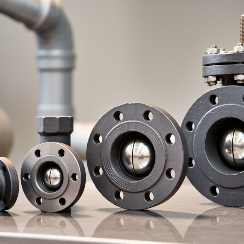
Cast-iron ball valves are often chosen for water systems and other moderate-duty service.
Their rigid bodies can provide dependable support when pressure, temperature, and operating conditions stay within the valve’s rated limits.
They may suit building services, irrigation, and some industrial lines.
Check the specifications carefully. Cast iron is relatively brittle, so impact, vibration, or sudden pressure changes deserve attention.
Ductile-iron ball valves use iron with a different graphite structure, which generally gives the body greater strength and impact resistance.
This can make them a practical option for demanding water and utility applications.
The material is tougher, not indestructible.
Performance still depends on the valve design, pressure class, seat material, and fluid compatibility.
A strong body cannot compensate for an unsuitable seal.
In the field, selection should start with the actual service conditions, not just the material name.
Note the working pressure, temperature range, fluid, and how often the valve will operate.
Confirm the manufacturer’s ratings and applicable test documentation.
I would not assume ductile iron is always the better choice; cost, corrosion protection, and installation conditions matter too.
One detail is easy to miss: a valve that fits the pipe may still be poorly matched to the process.
Floating-ball iron ball valves use a spherical closure held between two seats, rather than a shaft-supported trunnion design. Line pressure pushes the ball downstream against its seat, helping produce a tight shutoff. The mechanism is straightforward. These valves can suit smaller pipelines and moderate-pressure water, HVAC, and general process service, when body material and seals match the fluid. That detail matters. Iron alone does not guarantee corrosion resistance; coatings, liners, and seat materials affect service life.
For ductile-iron bodies, ASTM International’s ASTM A536 specification lists Grade 65-45-12 with minimum tensile strength of 65 ksi, yield strength of 45 ksi, and elongation of 12%. These are casting-material properties, not a valve pressure rating. Check the valve’s stated pressure-temperature limits separately. One practical caution: larger balls and higher differential pressures can increase seat loading and operating torque. Floating designs may therefore be less suitable than trunnion designs for some large-bore, high-pressure duties. They are also generally intended for on-off service, not continuous throttling. A real operating condition can expose what a catalogue description leaves out.
Trunnion-mounted iron ball valves support the ball with a stem and a lower trunnion. Unlike a floating-ball design, the ball does not rely on the seats alone for support. Pressure pushes the seats toward the ball, helping maintain a seal while limiting the load on the stem. That matters.
On a large water line, this arrangement can reduce operating torque and make actuation more practical. The difference is noticeable when a valve is operated often or fitted with an actuator. Yet lower torque does not guarantee a better valve. Seat material, pressure rating, temperature range, and the iron grade still need to match the service.
Iron bodies are commonly considered for water, building services, and other suitable utility applications. Check whether the body is gray iron or ductile iron; their properties differ, especially under impact or stress. A common selection mistake is focusing on the ball size while overlooking the pipeline’s pressure and operating cycle. The design also has more internal parts than some simpler valves, which can complicate inspection. It is worth checking access for maintenance before installation, not after a seat starts leaking.
The chart shows standard pipe outside diameters for selected NPS sizes, based on ASME B36.10M. Nominal pipe size is not the measured outside diameter, and these figures do not represent valve dimensions; check the valve’s published specifications when selecting a valve.
Full-port and reduced-port iron ball valves differ mainly in the opening through the ball. A full-port valve has a bore close to the inside diameter of the connected pipe. This creates less restriction when the valve is fully open. It can suit lines where pressure loss matters, such as a pump discharge or a process line carrying viscous fluid. The larger ball and body may add weight, cost, and installation space. Not always ideal.
A reduced-port valve has a smaller opening, so fluid speeds up as it passes through the valve. This can increase pressure loss, but the valve is often more compact and economical. For a simple isolation line, that trade-off may be acceptable. Compare the valve’s actual bore with the pipe’s inside diameter; nominal pipe size alone can be misleading. Check pressure and temperature ratings, seat materials, and end connections against the service conditions.
Both types are generally intended for open-or-closed operation, not continuous flow control. Leaving a ball valve partly open can wear the seats or create unwanted turbulence, depending on the design and fluid. Selection takes more than choosing “full” or “reduced.” A full-port valve does not automatically improve a system if nearby fittings already cause substantial restriction. Verify the manufacturer’s dimensional and performance data, and review the choice with a qualified piping professional when flow or safety requirements are critical.
Two-way iron ball valves provide a straight-through path for opening or shutting flow. They suit isolation points where a pipe needs a clear, simple route. A quarter-turn handle makes the position easy to check beside the line. Multiport designs add a third or fourth connection, letting operators divert flow or combine streams. Three-way valves commonly use L-port or T-port balls; the internal passage determines which ports connect at each handle position. Check the port diagram, not just the handle label. It is an easy detail to miss.
The connection rating also needs careful interpretation. ASME B16.1 lists gray-iron flange classes 25, 125, and 250; these describe flange ratings, not automatic pressure limits for a complete valve. The valve’s own published pressure-temperature rating must govern selection. For seat performance, ANSI/FCI 70-2 defines leakage classes and test procedures, with allowable leakage varying by class and valve size. A multiport valve may reduce fittings and joints, but its flow path can create unwanted cross-connection if the wrong ball pattern is specified. I would verify the flow diagram against the actual operating sequence before ordering. Short checks prevent awkward surprises.
„Thanks to the LUVIR technology, the solder resist process could be switched directly from the previously used mask exposure to direct exposure. As an outstanding digital solution on the market, this technology has been able to demonstrate fast process times and superior quality on our certified conventional ink in production. This allowed us to fully digitize the solder mask process at low cost – without process or ink adjustments. An excellent benefit to our production in Rot am See.“
Ralf Göhringer (Head of Production WE Rot am See)
I would definitely recommend the Limata machine and team for a future company purchase
Michael Greenaway
Compunetics Inc.
“The Limata ldi has been amazing!! Best thing we did was buy this machine”
Richard Brady
GM
Circuitlabs
“Since 2019, we have been running the Limata X1000 LDI system (including LUVIR for solder mask imaging) in daily production as an addition to our current process with film. The machine was capable of properly exposing Taiyo PSR-4000 BN (DI) solder mask types on normal to high-copper boards using a new and unique direct imaging process. The machine operating interface is very user friendly which allowed for a quick technical training curve. The pre-registration processing reduced several seconds of production time at every print. Limata support and service staff is incomparable. They supported our team every step of the way at basically any time of the day or night, with literally, an immediate response time, customizing the software interface to best fit our Operations and needs.
We have exposed more than 8,000 prints since end of October, on various solder mask colors and some resist film panels. Limata, has proven to be very capable and innovative. They are a strong contender in the industry.
We have very much enjoyed this project, and working with the team!
Thank you Limata for the continued support and being a part of our growth.”
Bill Sezate
Vice President, GM
Summit Interconnect
As a replacement to our current contact exposure process with film, the LIMATA X2000 system including LUVIR-Technology was capable of properly exposing non-LDI solder mask types using a direct imaging process. The machine offers cutting edge software with a very intuitive operating interface which allowed for quick technician training curve. The dual drawer system combined with pre-registration processing reduced several seconds of production time at every machine cycle. Limata support and service staff is world class. They added software patches to keep production running at shortest possible response times, customized the software interface to best fit our in-house Operations system, and even wrote a step-by-step machine processing manual. As a result of the project, we have exposed more than 16,000 times on various product types and solder mask brands/colors. Limata, in a very short timeframe as a company, has definitely shown they are truly innovative and will be challenging the industry of direct imaging for the top spot.
Kevin Beattie
Process Engineer
TTM Technologies
Forest Grove Division