Choosing the right Stick Welding Sticks can make the difference between a steady, manageable weld and a frustrating start. A rod that suits clean, mild-steel plate may behave poorly on rusty repairs or thick, restrained joints. Amperage, electrode diameter, base-metal thickness, welding position, and machine polarity all matter. Small details matter.
This guide compares common stick electrodes by the jobs they are designed to handle, from general-purpose maintenance to demanding structural work. It explains practical differences in arc behavior, penetration, slag removal, and moisture sensitivity, so you can match a rod to the conditions in front of you. A smooth bead is useful, but it does not prove a joint is sound. Preparation and technique still count.
No single electrode is best for every welder or workpiece. Even familiar rods can feel different when the fit-up changes, the steel is cold, or the power source is set incorrectly. That part is easy to underestimate. Use the electrode manufacturer’s specifications and the welding procedure for critical applications; confirm current range, polarity, and storage guidance before striking an arc. Where appropriate, test settings on scrap of similar material, then inspect the result rather than judging appearance alone. The recommendations ahead are meant to narrow the choices—not replace sound training, suitable protective equipment, or careful inspection.
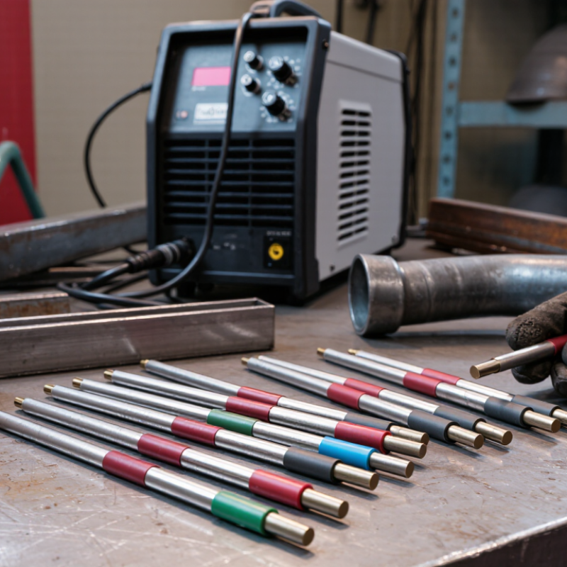
The E7018 marking is a compact guide, not a promise of a perfect weld. Under AWS A5.1, “E” identifies a covered electrode, while “70” indicates a minimum deposited-weld-metal tensile strength of 70,000 psi. That figure matters when matching filler metal to a job, but it does not establish the strength of the finished joint. Joint design, base-metal condition, fit-up, and welding procedure all matter too. A label cannot tell the whole story.
The remaining digits help narrow the choice. “1” indicates an all-position electrode, useful when a joint cannot be welded flat. “8” identifies a low-hydrogen iron-powder coating and the electrode’s usability with specified current types. Check the product data and the welding procedure before striking an arc; small differences matter. Keep the rod dry and follow its handling instructions, since moisture can undermine low-hydrogen performance. On the bench, the printed code may look simple beside a clamp and a steel coupon. It is easy to overfocus on “70.” I’d treat it as a starting point, then verify that the electrode suits the metal, position, and required procedure.
When choosing a stick electrode, read its AWS classification before comparing the coating or strength. In common four-digit labels such as E6011, the third numeral is the position indicator. A “1” means the electrode is classified for all positions: flat, horizontal, vertical, and overhead. That matters overhead. It tells you the rod is suitable for those orientations, not that every position will feel equally easy.
For example, an all-position electrode can help when a repair moves from a flat bench to a vertical bracket without changing rods. Watch the puddle closely: overhead work calls for controlled travel and a steady, manageable arc. A large diameter may be harder to handle on thin material, even when the position code allows it. The code does not choose the rod for you.
Match the position rating to the actual joint, then check the electrode’s packaging or technical sheet for its recommended current and polarity. Those details can vary by classification and size. Still, codes aren’t magic. A “1” is a useful starting point, but fit-up, metal thickness, and operator skill matter too. I would not assume one all-position stick is the best choice for every job; that’s an easy shortcut to regret.
The right electrode depends on the joint, position, and condition of the steel. E6010 makes a forceful, deeply penetrating arc and freezes quickly, which suits open-root work and vertical passes. It is commonly used with DC, but it demands steady control. E6011 offers similar digging action and can run on AC, making it useful when a DC machine is unavailable. Both can handle less-than-pristine surfaces, though cleaning the metal still improves weld quality.
For lighter sheet and general repairs, E6013 usually gives a softer arc and a smoother bead with less penetration. That can help limit burn-through on thin material. E7018 is a low-hydrogen choice for stronger joints, including structural work, when the base metal is properly prepared. Keep the rods dry and follow the storage instructions; moisture can contribute to weld defects. Small details matter.
E7024 deposits metal quickly and works well on flat or horizontal fillet welds, such as long seams on plate. Its high deposition rate is less useful overhead or on vertical joints. Match the rod to the machine’s output and the welding position, then check the applicable procedure for critical work. A rod that feels easy on one joint may perform poorly on another. I’d still make a test bead before committing to a long seam.
Compare the AWS-classification minimum tensile strength of E6010, E6011, E6013, E7018, and E7024.
Tensile-strength values are minimum classification values in thousands of pounds per square inch (ksi). Select an electrode and welding procedure suited to the base metal, joint, position, and applicable code.
Choose rod diameter and amperage together, not by habit. The American Welding Society’s AWS A5.1/A5.1M:2023 classifies covered carbon-steel electrodes, but does not set one universal amperage for each diameter. Check the electrode’s technical data sheet: its operating range can change with polarity, position, and technique. Published data sheets commonly place a 1/8-inch E7018 electrode near 90–150 A, though the exact range varies. Small changes matter.
Tips: Begin near the middle of the specified range, then adjust in small steps. A stable arc should sound even and leave a manageable puddle. If the rod sticks repeatedly, current may be too low; excessive spatter or an undercut edge can signal settings that are too high. Check the data sheet before changing diameter or amperage.
On a thin plate, a larger rod may put in heat too quickly, even when the machine can supply the listed current. On thicker material, a small rod may demand multiple passes. I’ve seen a bead look tidy while still showing poor fusion at the edge; appearance alone is not proof. Record rod size, polarity, and machine setting so the next pass starts from evidence, not guesswork.
| Electrode classification | Common job fit | Diameter | Typical amperage | Typical current / polarity | Position notes |
|---|---|---|---|---|---|
| E6010 | Deep-penetrating welds on clean or rusty carbon steel; root passes and pipe work | 3/32 in (2.4 mm) | 40–85 A | Usually DCEP | All positions, including vertical-down when appropriate |
| E6010 | Deep-penetrating welds on carbon steel; root passes and pipe work | 1/8 in (3.2 mm) | 75–135 A | Usually DCEP | All positions, including vertical-down when appropriate |
| E6011 | General repair and maintenance; useful where AC output is needed | 3/32 in (2.4 mm) | 40–85 A | AC or DCEP, depending on electrode specification | All positions |
| E6011 | General repair and maintenance on carbon steel | 1/8 in (3.2 mm) | 75–135 A | AC or DCEP, depending on electrode specification | All positions |
| E6013 | Light fabrication, sheet metal, and general-purpose welding with a smoother bead | 3/32 in (2.4 mm) | 40–90 A | Often AC, DCEP, or DCEN; check the electrode specification | All positions; smaller diameters suit thinner material |
| E6013 | General fabrication and repair on carbon steel | 1/8 in (3.2 mm) | 80–130 A | Often AC, DCEP, or DCEN; check the electrode specification | All positions |
| E7018 | Structural and general fabrication where low-hydrogen electrodes are specified | 3/32 in (2.4 mm) | 70–110 A | Usually DCEP; some versions are rated for AC | All positions; follow storage and handling requirements |
| E7018 | Structural and general fabrication where low-hydrogen electrodes are specified | 1/8 in (3.2 mm) | 90–160 A | Usually DCEP; some versions are rated for AC | All positions |
| E7024 | High-deposition fillet and groove welds on thicker carbon steel | 1/8 in (3.2 mm) | 100–160 A | AC or DC; polarity depends on electrode specification | Primarily flat and horizontal fillet positions |
| E7024 | Higher-deposition welding on thicker material in suitable positions | 5/32 in (4.0 mm) | 150–220 A | AC or DC; polarity depends on electrode specification | Primarily flat and horizontal fillet positions |
Amperage ranges are representative starting points, not universal settings. Actual operating ranges vary by electrode manufacturer, diameter, welding position, joint design, and power source. Always follow the electrode packaging or technical data sheet, the approved welding procedure, and applicable safety requirements.
Top Stick Welding Sticks for Every Welding Job
For crack-sensitive joints, check the hydrogen designation, not just the electrode’s strength or position rating. Under AWS A5.1/A5.1M and AWS A5.5/A5.5M classifications, H4 indicates a maximum diffusible hydrogen level of 4 mL per 100 g of deposited weld metal. AWS A4.3 provides the standard test methods used to measure diffusible hydrogen in ferritic steel weld metal. That number matters. It helps engineers select electrodes for restrained joints, thick sections, or steels prone to hydrogen-assisted cracking.
H4 describes test results under controlled conditions, not a promise that every field weld will contain exactly that amount. Damp storage, a long-open electrode container, oily plate edges, and a humid morning can all undermine careful selection. Follow the electrode maker’s handling and rebaking instructions, and keep opened low-hydrogen electrodes in suitable heated storage. Clean the joint, too. A perfect classification cannot fix contamination.
The risk also depends on the steel’s susceptibility, joint restraint, and welding conditions; hydrogen is only one part of the problem. For a high-restraint repair, pair an H4 electrode with an appropriate preheat and a documented welding procedure. I still think the suffix gets treated as a shortcut too often. It is useful evidence, but not a substitute for checking the actual joint and handling records.
„Thanks to the LUVIR technology, the solder resist process could be switched directly from the previously used mask exposure to direct exposure. As an outstanding digital solution on the market, this technology has been able to demonstrate fast process times and superior quality on our certified conventional ink in production. This allowed us to fully digitize the solder mask process at low cost – without process or ink adjustments. An excellent benefit to our production in Rot am See.“
Ralf Göhringer (Head of Production WE Rot am See)
I would definitely recommend the Limata machine and team for a future company purchase
Michael Greenaway
Compunetics Inc.
“The Limata ldi has been amazing!! Best thing we did was buy this machine”
Richard Brady
GM
Circuitlabs
“Since 2019, we have been running the Limata X1000 LDI system (including LUVIR for solder mask imaging) in daily production as an addition to our current process with film. The machine was capable of properly exposing Taiyo PSR-4000 BN (DI) solder mask types on normal to high-copper boards using a new and unique direct imaging process. The machine operating interface is very user friendly which allowed for a quick technical training curve. The pre-registration processing reduced several seconds of production time at every print. Limata support and service staff is incomparable. They supported our team every step of the way at basically any time of the day or night, with literally, an immediate response time, customizing the software interface to best fit our Operations and needs.
We have exposed more than 8,000 prints since end of October, on various solder mask colors and some resist film panels. Limata, has proven to be very capable and innovative. They are a strong contender in the industry.
We have very much enjoyed this project, and working with the team!
Thank you Limata for the continued support and being a part of our growth.”
Bill Sezate
Vice President, GM
Summit Interconnect
As a replacement to our current contact exposure process with film, the LIMATA X2000 system including LUVIR-Technology was capable of properly exposing non-LDI solder mask types using a direct imaging process. The machine offers cutting edge software with a very intuitive operating interface which allowed for quick technician training curve. The dual drawer system combined with pre-registration processing reduced several seconds of production time at every machine cycle. Limata support and service staff is world class. They added software patches to keep production running at shortest possible response times, customized the software interface to best fit our in-house Operations system, and even wrote a step-by-step machine processing manual. As a result of the project, we have exposed more than 16,000 times on various product types and solder mask brands/colors. Limata, in a very short timeframe as a company, has definitely shown they are truly innovative and will be challenging the industry of direct imaging for the top spot.
Kevin Beattie
Process Engineer
TTM Technologies
Forest Grove Division