A Laser Quenching Machine uses a focused beam to heat selected metal surfaces, then lets the surrounding material cool them rapidly. The result is a hardened surface with a comparatively tough core. Picture a bright, moving spot tracing a gear tooth while nearby areas remain cooler. It is controlled heat treatment, not a magic coating. Material grade, beam power, travel speed, and focus all affect the outcome.
The business case depends on repeatable results. The International Federation of Robotics’ World Robotics 2024 report counted 4,281,585 industrial robots operating in factories worldwide in 2023, up 10% from 2022. That figure describes factory automation broadly, not laser quenching alone. Still, it helps explain why manufacturers value processes that can be monitored and integrated into production cells. Theodore Maiman, the laser pioneer, is often attributed the line, “A laser is a solution looking for a problem.” It is a useful reminder: the machine should solve a defined wear or distortion issue, not merely look advanced.
In practice, engineers assess the component’s geometry, steel composition, target hardness, and production volume before choosing a system. A narrow gear edge may need different beam delivery than a broad shaft surface. Results also depend on setup and verification. Small variations matter. This overview will explain how the equipment works, where it fits, and what buyers should check. One caveat: published performance claims can be difficult to compare unless test conditions are disclosed.
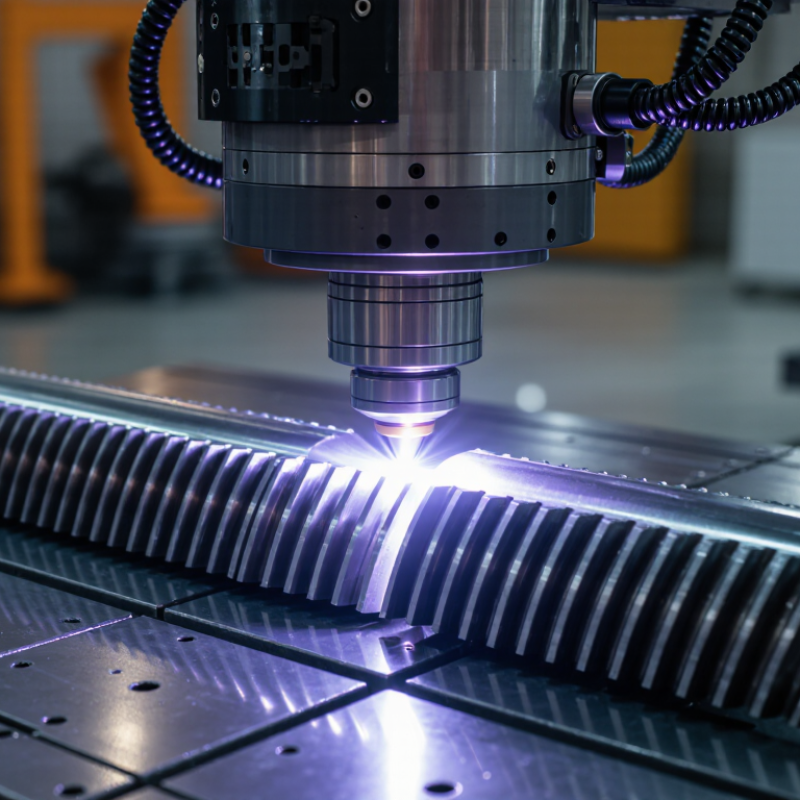
A laser quenching machine heats a selected steel surface with a focused beam, changing its microstructure without heating the whole component. In suitable steels, the heated layer reaches the austenitizing range; rapid cooling then forms hard martensite. The cooler material beneath draws heat away, creating the self-quenching effect. No liquid quench is normally needed. The result is a hard wear-resistant surface over a tougher core.
TWI’s technical guidance on laser surface hardening gives typical hardened depths of about 0.1–2 mm, depending on material and process settings. That range matters: a gear tooth and a thin shaft may respond very differently to the same beam. ASM Handbook, Volume 4A, explains that steel composition and thermal history govern transformation and final hardness; a machine setting alone cannot guarantee either. Operators therefore check beam power, travel speed, focus, and surface condition, then verify hardness and case depth on the actual part. Small variations count. Even a bright surface can conceal uneven heating. In practice, process windows sometimes need adjustment after inspection, which is less elegant than a perfect first pass—but more reliable.
What Is a Laser Quenching Machine?
A laser quenching machine hardens selected metal surfaces by heating them with a focused beam. Its architecture brings together a laser source, beam-delivery optics, controlled motion, and cooling systems. Each part affects the finished hardened zone.
The laser source provides energy, while lenses and protective windows shape and guide the beam. Optics must stay clean and correctly aligned; even a small contaminant can affect energy delivery. Small details matter. A CNC axis or robot moves the beam or workpiece along a programmed path. The motion system controls travel speed, position, and overlap between passes. In practice, corners and changing surface heights can make uniform treatment harder than a flat test piece suggests.
Cooling has two roles. A chiller removes heat from the laser source and other temperature-sensitive components. The treated metal usually cools through heat conduction into the surrounding material, rather than through a separate quenching bath. Cooling capacity, coolant flow, and temperature monitoring help keep the equipment stable during operation. Settings still need validation on the actual part. Geometry, alloy, surface condition, and beam focus can all change the result, so a successful setup may not transfer unchanged to another component.
Machine Architecture: Laser Source, Optics, CNC Motion, and Cooling
Representative wavelengths vary by source design. Wavelength influences the choice of beam-delivery optics and how energy couples into the workpiece. CNC motion controls the beam path, while cooling removes heat from the laser source and other temperature-sensitive components.
A laser quenching machine heats a metal surface with a focused beam. The cooler underlying material then removes heat quickly. This rapid cycle can harden selected areas while leaving nearby regions comparatively unchanged. Control matters.
Typical process power densities may range from 10³–10⁵ W/cm², but this is not a universal setting. The lower end may suit slower heating or broader spots; the upper end can deliver intense energy to a small area. Actual results depend on alloy composition, surface condition, beam size, scan speed, and how well the surface absorbs the wavelength. A shiny surface may reflect more energy than a dark, prepared one.
Operators monitor the hardened track, not just the power display. Too little energy may produce a shallow or inconsistent hardened layer; too much can cause melting, roughness, or unwanted distortion. Temperature checks and test coupons help establish a useful process window. It is tempting to treat the stated range as a recipe. Numbers alone mislead. Real parts often need adjustment after inspection, and even a small change in focus can shift the result. A reliable setup records settings alongside hardness and case-depth measurements.
A laser quenching machine hardens selected areas by heating a metal surface with a focused laser beam. The cooler material beneath the surface draws heat away, forming a hardened layer without requiring a separate quench bath. This makes the process useful for wear-prone areas such as gear teeth, guide rails, and shaft edges. The beam can follow a defined path, though setup still takes care.
Typical case depths range from 0.1 to 2 mm, with hardness often reaching 50–65 HRC on suitable steels. These figures are not guaranteed settings. Alloy composition, starting condition, beam power, travel speed, and part geometry all affect the result. A thin layer may suit a small contact surface; a deeper case may be needed for heavier wear. Check hardness and depth on a representative sample. The range looks tidy on paper, but real parts can vary.
Tips: Specify the steel grade and target wear area before processing. Inspect for distortion or cracking, especially near sharp corners. Record test results, then adjust the process if needed. One detail is easy to miss: hardness alone does not confirm adequate case depth.
A laser quenching machine heats a steel surface rapidly, then relies on the surrounding material to draw heat away. The result is a hardened layer, often without immersing the whole part. ASM Handbook, Volume 4A, describes laser transformation hardening as a surface process; published industrial data commonly show hardened depths around 0.2–1.5 mm, depending on power, speed, and steel composition. Treat that range as a guide, not a guarantee. Medium-carbon and alloy steels, such as 1045 and 4140, are common candidates because they can form hard martensite. Low-carbon steel may not achieve useful hardness without additional preparation.
Geometry matters just as much. A broad, accessible shaft surface is easier to scan evenly than a narrow groove or sharp tooth root. Corners can overheat, while heavy sections pull heat away and may reduce depth. Not every corner.
Reflective finishes, scale, and inconsistent surface condition can also disturb energy absorption. Process windows depend on beam size, overlap, traverse speed, and prior heat treatment; small changes can leave soft bands or create cracking risk. ISO 15787:2016 addresses heat-treated steel components and their documentation, underscoring the need to record treatment conditions and inspection results.
A practical trial should measure hardness across the surface and through a cut section. The awkward part is that a clean-looking surface proves little.
„Thanks to the LUVIR technology, the solder resist process could be switched directly from the previously used mask exposure to direct exposure. As an outstanding digital solution on the market, this technology has been able to demonstrate fast process times and superior quality on our certified conventional ink in production. This allowed us to fully digitize the solder mask process at low cost – without process or ink adjustments. An excellent benefit to our production in Rot am See.“
Ralf Göhringer (Head of Production WE Rot am See)
I would definitely recommend the Limata machine and team for a future company purchase
Michael Greenaway
Compunetics Inc.
“The Limata ldi has been amazing!! Best thing we did was buy this machine”
Richard Brady
GM
Circuitlabs
“Since 2019, we have been running the Limata X1000 LDI system (including LUVIR for solder mask imaging) in daily production as an addition to our current process with film. The machine was capable of properly exposing Taiyo PSR-4000 BN (DI) solder mask types on normal to high-copper boards using a new and unique direct imaging process. The machine operating interface is very user friendly which allowed for a quick technical training curve. The pre-registration processing reduced several seconds of production time at every print. Limata support and service staff is incomparable. They supported our team every step of the way at basically any time of the day or night, with literally, an immediate response time, customizing the software interface to best fit our Operations and needs.
We have exposed more than 8,000 prints since end of October, on various solder mask colors and some resist film panels. Limata, has proven to be very capable and innovative. They are a strong contender in the industry.
We have very much enjoyed this project, and working with the team!
Thank you Limata for the continued support and being a part of our growth.”
Bill Sezate
Vice President, GM
Summit Interconnect
As a replacement to our current contact exposure process with film, the LIMATA X2000 system including LUVIR-Technology was capable of properly exposing non-LDI solder mask types using a direct imaging process. The machine offers cutting edge software with a very intuitive operating interface which allowed for quick technician training curve. The dual drawer system combined with pre-registration processing reduced several seconds of production time at every machine cycle. Limata support and service staff is world class. They added software patches to keep production running at shortest possible response times, customized the software interface to best fit our in-house Operations system, and even wrote a step-by-step machine processing manual. As a result of the project, we have exposed more than 16,000 times on various product types and solder mask brands/colors. Limata, in a very short timeframe as a company, has definitely shown they are truly innovative and will be challenging the industry of direct imaging for the top spot.
Kevin Beattie
Process Engineer
TTM Technologies
Forest Grove Division
