Bulk cement handling can appear straightforward: move powder from a ship, railcar, or truck into storage. In practice, fine cement dust, changing material flow, and tight delivery schedules make the transfer point critical. A Cement Unloader helps move cement from bulk carriers while managing dust and keeping material flow controlled. Its design may use pneumatic conveying, mechanical handling, or a combination, depending on the site and operating needs.
The details matter. A well-matched unloader can reduce spillage, limit dust exposure, and feed storage silos more consistently. Enclosed transfer points, suitable filters, and accessible inspection areas all contribute to reliable operation. Small leaks add up. Still, no machine eliminates every problem: damp material, poor maintenance, or an unsuitable conveying rate can interrupt discharge. Operators should assess capacity, material characteristics, berth layout, energy use, and maintenance access before choosing equipment. Actual performance depends on these conditions, so supplier specifications should be checked against the site’s requirements rather than treated as guarantees.
Why is this equipment essential for bulk handling? Because unloading is not merely a transfer step; it affects cleanliness, efficiency, and the reliability of the wider supply chain. A practical evaluation considers both the machine and the people who operate it. That point is easy to overlook. This guide examines how cement unloaders work, which features influence performance, and what questions buyers should ask before investing.
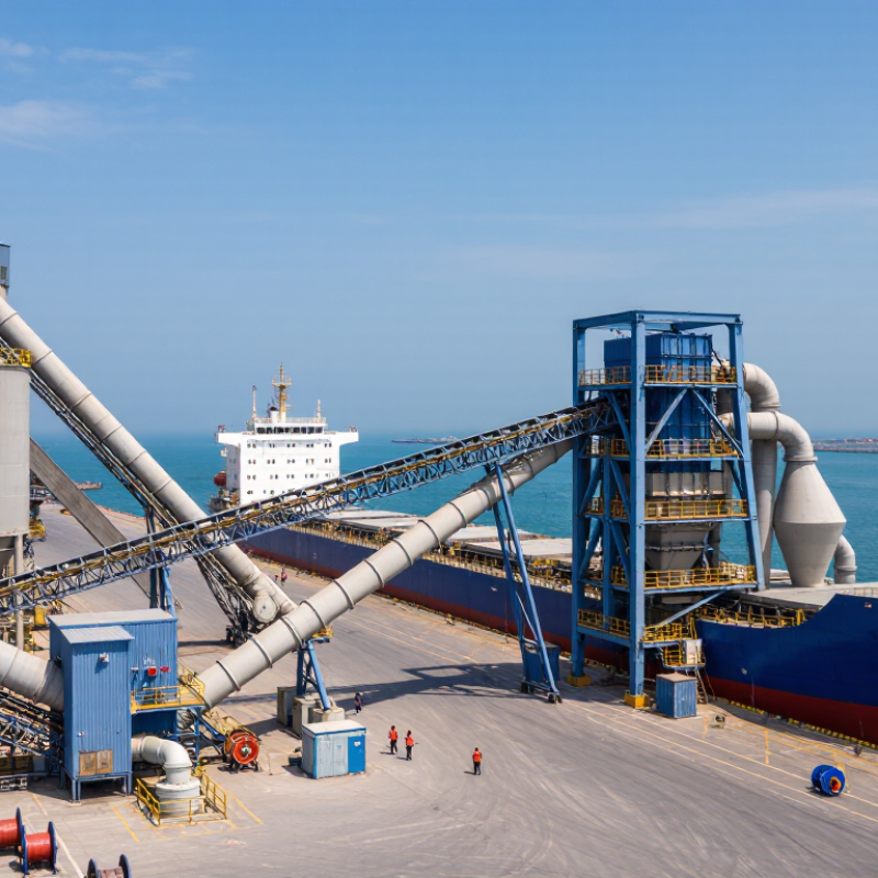
A cement unloader connects the delivery point to the rest of the bulk-handling system. At a port, it transfers cement from a vessel into a hopper, then toward conveyors, storage silos, or other conveying equipment. The handoff matters: an uneven flow can leave downstream equipment waiting or overload a transfer point. Even a short interruption can affect the delivery schedule.
The unloader’s performance depends on the whole route, not just its rated capacity. Hopper design, conveyor speed, silo space, and dust-control equipment all shape how reliably material moves. Operators also need clear access to inspection points and practical procedures for clearing blockages. Cement is fine and can become airborne, so enclosed transfer points and suitable extraction help limit dust. That matters.
In practice, the handoff is rarely perfect. A delivery may arrive faster than a silo can accept it, or a conveyor may need maintenance at the wrong moment. Planning for these constraints helps teams choose an unloader that suits actual operating conditions, rather than a capacity figure alone. Small details count: a poorly placed chute can create buildup, while a clear inspection routine can catch wear before it disrupts transfer.
Pneumatic and mechanical cement unloaders move powder from ships, railcars, or trucks into storage. The right method depends on the transfer distance, required rate, and site layout. Cement is fine and dusty, so sealed connections and controlled airflow matter at every handoff.
A pneumatic unloader uses a blower or vacuum system to carry cement through enclosed pipes. The operator connects a flexible hose to the discharge point, then monitors pressure and airflow as powder travels to a silo. It can reach around obstacles and serve several receiving points. But wet cement or a poorly sealed joint can reduce flow and create dust. Small details matter.
A mechanical unloader uses equipment such as screws, chains, or bucket conveyors to move cement along a fixed path. These systems can provide steady, high-volume transfer, especially where the route is short and predictable. Their moving parts need inspection; worn seals or bearings may interrupt a shift. Mechanical layouts are less flexible, though often easier to understand at a glance. Neither method is automatically better. Operators should compare material condition, maintenance access, and the actual unloading cycle—not just the rated capacity. I would still leave room for site-specific testing, because real cement does not always behave like a clean diagram.
Why Is a Cement Unloader Essential for Bulk Handling?
Portland cement is commonly associated with a specific gravity near 3.15, measured using ASTM C188. This value compares cement’s particle density with water; it is not the density of cement in a silo. Air between particles changes the bulk density considerably. That distinction matters.
A cement unloader must handle steady flow without relying on specific gravity alone. Engineers also consider silo geometry, conveying distance, target throughput, and the cement’s tendency to compact or form arches. A narrow outlet may restrict discharge, even when the equipment’s rated capacity looks adequate. Load cells and flow tests can help verify performance under real operating conditions.
The number 3.15 still informs equipment design. It helps estimate the mass of solid cement occupying a known particle volume, supporting checks on structural loads and material balance. But actual operating loads depend on aeration, moisture, and packing. Small details count. I would treat the ASTM value as a useful reference, not a complete design answer; field measurements can expose assumptions that calculations miss. A reliable unloader pairs appropriate conveying capacity with controlled discharge and practical access for inspection.
Designing around cement’s typical specific gravity of 3.15, as measured for hydraulic cement using ASTM C188.
What this means: At equal solid-particle volumes, typical Portland cement is about 3.15 times as dense as water. This is particle density, not loose bulk density; air between particles makes bulk cement less dense. A purpose-designed unloader helps manage cement flow during transfer and storage.
A cement unloader must handle more than a vessel’s discharge rate. Loose bulk density determines how much cement each cubic metre represents. The Conveyor Equipment Manufacturers Association’s Belt Conveyors for Bulk Materials lists Portland cement at roughly 70–94 lb/ft³, or 1.12–1.51 t/m³. This supports using about 1.0–1.5 t/m³ as a practical planning range, not a guaranteed value for every shipment.
The difference matters. At 100 m³ per hour, that range corresponds to roughly 100–150 tonnes per hour before operating losses. A system sized only by volume could therefore miss the required mass throughput. Density also changes with aeration and handling conditions. Cement may look fluffy at the outlet, then settle in a receiving hopper. Small details count: a long discharge hose, a partly restricted filter, or uneven airflow can reduce the actual rate. Check the supplier’s material data and confirm performance under site conditions. A neat calculation is useful, but it can still be wrong. Bulk density should be verified, especially when sizing the unloader, conveying line, and storage inlet.
| Handling Consideration | Typical Information | Why It Matters for Unloader Selection |
|---|---|---|
| Loose bulk density | About 1.0–1.5 t/m³; the actual value depends on cement type, packing, and aeration. | Density affects the relationship between volume and mass, so equipment capacity should be checked in both m³/h and t/h. |
| Flow behavior | Fine cement can be cohesive and may compact during storage or handling. | An appropriately designed intake and conveying system helps reduce the risk of bridging, uneven flow, and interruptions. |
| Dust control | Dry cement can become airborne during transfer and discharge. | Enclosed transfer points and suitable dust-collection provisions help limit dust release and maintain a cleaner work area. |
| Moisture sensitivity | Cement can absorb moisture and may form lumps when exposed to damp conditions. | Weather protection and well-sealed transfer connections help preserve material flow and reduce product loss. |
| Throughput requirements | Required unloading rate varies with vessel size, receiving-system capacity, and operating schedule. | Matching the unloader’s rated capacity to the full transfer route helps prevent bottlenecks downstream. |
| Material containment | Transfer interfaces may produce dust if connections are open or poorly sealed. | Contained connections help control emissions and reduce spillage around the unloading point. |
| Equipment compatibility | Unloading arrangements differ by storage layout, conveying distance, and discharge-point location. | Checking site geometry and the receiving system before selection supports reliable integration. |
Density figures are indicative; confirm the material’s measured bulk density and operating conditions when sizing equipment.
A cement unloader does more than move powder from a truck into a silo. It must contain dust at the connection point, where dry cement can escape during hose coupling or pressure changes. Enclosed transfer lines and correctly sized dust collection help limit airborne material. Small leaks matter. Operators should inspect seals, clamps, and filter condition, not just the main equipment.
Moisture is another practical concern. Damp cement can cake inside a hose or form a blockage near a bend, slowing discharge and increasing pressure. Keep transfer connections protected from rain, and check that filters are clean and dry. Even careful handling cannot fix cement that arrived wet, so the receiving process needs a way to pause and investigate unusual flow. That step can feel inconvenient, but forcing a blockage may create a bigger problem.
Capacity should match the receiving silo, delivery schedule, and actual transfer rate. A high-rated unloader is not useful if the silo fills faster than staff can monitor it. Controls should show pressure, silo level, and filter condition, with alarms or shutdowns for abnormal readings. Clear, accessible controls also help during shift changes. A system may look adequate on paper; real unloading conditions deserve a second look.
„Thanks to the LUVIR technology, the solder resist process could be switched directly from the previously used mask exposure to direct exposure. As an outstanding digital solution on the market, this technology has been able to demonstrate fast process times and superior quality on our certified conventional ink in production. This allowed us to fully digitize the solder mask process at low cost – without process or ink adjustments. An excellent benefit to our production in Rot am See.“
Ralf Göhringer (Head of Production WE Rot am See)
I would definitely recommend the Limata machine and team for a future company purchase
Michael Greenaway
Compunetics Inc.
“The Limata ldi has been amazing!! Best thing we did was buy this machine”
Richard Brady
GM
Circuitlabs
“Since 2019, we have been running the Limata X1000 LDI system (including LUVIR for solder mask imaging) in daily production as an addition to our current process with film. The machine was capable of properly exposing Taiyo PSR-4000 BN (DI) solder mask types on normal to high-copper boards using a new and unique direct imaging process. The machine operating interface is very user friendly which allowed for a quick technical training curve. The pre-registration processing reduced several seconds of production time at every print. Limata support and service staff is incomparable. They supported our team every step of the way at basically any time of the day or night, with literally, an immediate response time, customizing the software interface to best fit our Operations and needs.
We have exposed more than 8,000 prints since end of October, on various solder mask colors and some resist film panels. Limata, has proven to be very capable and innovative. They are a strong contender in the industry.
We have very much enjoyed this project, and working with the team!
Thank you Limata for the continued support and being a part of our growth.”
Bill Sezate
Vice President, GM
Summit Interconnect
As a replacement to our current contact exposure process with film, the LIMATA X2000 system including LUVIR-Technology was capable of properly exposing non-LDI solder mask types using a direct imaging process. The machine offers cutting edge software with a very intuitive operating interface which allowed for quick technician training curve. The dual drawer system combined with pre-registration processing reduced several seconds of production time at every machine cycle. Limata support and service staff is world class. They added software patches to keep production running at shortest possible response times, customized the software interface to best fit our in-house Operations system, and even wrote a step-by-step machine processing manual. As a result of the project, we have exposed more than 16,000 times on various product types and solder mask brands/colors. Limata, in a very short timeframe as a company, has definitely shown they are truly innovative and will be challenging the industry of direct imaging for the top spot.
Kevin Beattie
Process Engineer
TTM Technologies
Forest Grove Division