A Multilayer Pcb Board can help a project fit more circuitry into a limited space. Instead of spreading every connection across one surface, designers use several copper layers separated by insulating material. A compact controller, for example, may need room for a processor, memory, power circuits, and communication lines. Multiple layers can make these connections easier to route, though they do not automatically make a design better. Every added layer brings more decisions about stack-up, materials, manufacturing, and cost.
The right choice depends on the board’s function and the conditions it must handle. A multilayer design may support denser routing, shorter connections, and more deliberate separation of signals and power. It can also create challenges: repairs may be difficult, and a poor layer arrangement can undermine signal quality or thermal performance. Details matter. Before choosing, engineers typically consider component density, operating frequency, current demands, board dimensions, production volume, and the fabricator’s capabilities. A simple prototype may not need extra layers. That is worth questioning.
This guide explores why a Multilayer Pcb Board may suit one project but not another. It looks at practical benefits, design trade-offs, and manufacturing considerations without treating layer count as a measure of quality. Real layouts rarely follow a perfect plan; connector placement or a late component change can force revisions. Careful planning helps, but review and testing still matter. The goal is a board that works reliably, can be manufactured consistently, and meets the project’s needs—not simply one with more layers.
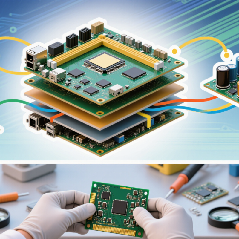
A multilayer PCB board is a circuit board built from three or more conductive copper layers separated by insulating material. These layers are pressed together into one compact structure. The outer layers usually carry components and visible traces, while inner layers can route signals or distribute power and ground. Tiny plated holes, called vias, connect selected layers. Think of it as several carefully planned wiring maps stacked inside one board.
This structure helps fit more connections into a smaller area. It can also provide dedicated ground planes, which may improve signal stability and reduce electrical noise when the layout is designed well. A compact network router or industrial controller might use multiple layers to connect dense components without long surface traces. More layers are not automatically better, though. Extra layers add manufacturing complexity, and a poor stack-up can create problems rather than solve them. I have seen simple designs become harder to troubleshoot after unnecessary routing layers were added.
Tips: Decide what each layer will do before routing. Keep sensitive signal paths away from noisy power sections where practical. Ask your fabricator to review the layer stack, copper thickness, and minimum via dimensions. Small details matter. Leave room for testing, too; a board that works electrically can still be awkward to inspect or repair.
A multilayer PCB is built by bonding several copper layers with insulating material into one compact board. The copper layers carry signals, power, and ground; the insulating layers keep them separated. A typical stackup may place signal layers near a continuous ground plane, helping control electrical noise and provide a predictable return path. The exact arrangement depends on the circuit, not simply the number of layers.
Inside the board, thin copper foil is laminated with cured fiberglass and resin, often called prepreg. A solid core may sit between these layers. Drilled holes, called vias, connect selected copper layers. Plated barrels line the holes, while blind or buried vias connect only some layers. Small details matter. A misplaced via can interrupt a ground plane or create an awkward signal path. Designers therefore plan layer order, copper thickness, dielectric spacing, and trace width together, especially when controlling impedance for fast signals. A neat drawing is not enough.
I have seen stackups that looked efficient on screen but left too little room for routing after manufacturing limits were considered. That is a useful reminder: layer count alone does not guarantee a reliable board. Review the stackup with the fabricator, check the proposed materials and via sizes, and leave practical spacing for real production variation.
Multilayer PCB boards place several copper circuits inside one compact board, connected through plated holes called vias. This structure can save space when a design needs dense routing, such as a controller handling sensors, memory, and power signals. Shorter, more direct connections may also help manage signal interference and maintain consistent performance. The difference becomes clear when a crowded single-layer layout would otherwise require long traces or awkward wire links.
More room inside.
That matters in small devices. Separate layers can keep sensitive signals away from noisy power paths, while a
Multilayer PCB boards are common in products that must fit dense circuits into limited space. Smartphones, network equipment, industrial controllers, and medical imaging systems often need several signal layers, dedicated power planes, and controlled routing. A compact board can connect processors, memory, sensors, and communication components without long, crossing traces. That matters when a device must manage heat, reduce electrical interference, or maintain signal quality. The trade-off is real: more layers can raise fabrication cost and make inspection harder. More layers are not automatically better.
Automotive electronics are another clear use case, including battery management, driver-assistance systems, and in-vehicle displays. The International Energy Agency’s Global EV Outlook 2024 reported that electric car sales exceeded 17 million in 2024, representing more than one in five cars sold worldwide. This growth increases demand for electronic systems that monitor batteries and coordinate vehicle functions. High-reliability multilayer boards can help route those circuits in a compact space, though the board design must match the vehicle’s vibration, temperature, and service-life requirements. Aerospace and telecom projects also use multilayer designs when weight, footprint, and signal performance matter. The right layer count depends on the actual circuit and operating environment, not just the product category.
Multilayer PCBs are commonly used when a project needs compact routing, higher circuit density, or controlled signal integrity. The ranges shown are indicative design examples, not fixed requirements; actual layer counts depend on the product and its electrical and mechanical constraints.
Choosing a layer count starts with the circuit, not a preference for “more.” List the signals, supply rails, connectors, and peak data rates. Then check whether the layout can provide continuous reference planes and short return paths. IPC-2221A offers general printed-board design guidance, but it does not prescribe one layer count for every design. Your stack-up must fit the actual geometry.
Prismark’s 2024 industry analysis put global PCB production value at about $73.8 billion in 2024, showing the scale and variety of board designs—not a reason to add layers. For a compact controller with modest routing needs, four layers may provide practical signal and power planes. Dense packages, controlled-impedance links, or strict noise limits may justify six or more. Ask your fabricator to review drill sizes, copper weights, and impedance targets before fixing the stack-up. Small details matter.
Compare a two-layer layout with a proposed multilayer version using real placement and routing data. Check congestion, return-current paths, thermal needs, and prototype cost. A layer added late can force connector or via changes. That happens. More layers can improve routing freedom, but they also increase fabrication complexity and may hide a weak floorplan. Record the assumptions, then revisit them after the first routing pass.
| Typical Layer Count | Common Project Fit | Routing and Design Capacity | Potential Advantages | Key Considerations |
|---|---|---|---|---|
| 2 layers | Simple controls, basic consumer electronics, and low-density circuits | Components and traces are placed on both outer copper layers | Straightforward stack-up and often a cost-effective choice for uncomplicated designs | Limited routing space can make compact layouts and signal separation more difficult |
| 4 layers | Moderate-density embedded systems, communications devices, and mixed-signal products | Two outer routing layers can be combined with internal power, ground, or signal layers | More routing flexibility; continuous reference planes can support return paths and reduce coupling when designed appropriately | Requires a considered stack-up and attention to plane continuity and decoupling |
| 6 layers | Denser digital boards, products with several interfaces, and designs with tighter signal-integrity needs | Additional internal routing layers provide more options for separating signals and planes | Can help manage routing congestion and provide useful reference-plane arrangements | Higher fabrication complexity; layer arrangement should be reviewed with the fabricator |
| 8 layers | High-density digital systems, advanced networking equipment, and compact industrial electronics | Multiple internal signal and plane layers support complex routing and layer-to-layer allocation | More freedom to organize signal groups, power distribution, and reference planes | Added layers do not automatically improve performance; stack-up, routing, and manufacturing tolerances matter |
| 10 or more layers | Very high-density, feature-rich, or space-constrained designs with substantial routing demands | Many signal and plane layers can accommodate complex interconnects and dense component layouts | Enables extensive routing options where simpler layer counts cannot meet design requirements | Typically involves greater fabrication complexity, cost, and design-for-manufacturing requirements |
Selection tip: Choose the lowest layer count that satisfies routing density, electrical performance, mechanical constraints, and manufacturing requirements. Confirm the proposed stack-up, minimum trace and spacing rules, via options, and impedance requirements with the PCB fabricator before finalizing the design.
„Thanks to the LUVIR technology, the solder resist process could be switched directly from the previously used mask exposure to direct exposure. As an outstanding digital solution on the market, this technology has been able to demonstrate fast process times and superior quality on our certified conventional ink in production. This allowed us to fully digitize the solder mask process at low cost – without process or ink adjustments. An excellent benefit to our production in Rot am See.“
Ralf Göhringer (Head of Production WE Rot am See)
I would definitely recommend the Limata machine and team for a future company purchase
Michael Greenaway
Compunetics Inc.
“The Limata ldi has been amazing!! Best thing we did was buy this machine”
Richard Brady
GM
Circuitlabs
“Since 2019, we have been running the Limata X1000 LDI system (including LUVIR for solder mask imaging) in daily production as an addition to our current process with film. The machine was capable of properly exposing Taiyo PSR-4000 BN (DI) solder mask types on normal to high-copper boards using a new and unique direct imaging process. The machine operating interface is very user friendly which allowed for a quick technical training curve. The pre-registration processing reduced several seconds of production time at every print. Limata support and service staff is incomparable. They supported our team every step of the way at basically any time of the day or night, with literally, an immediate response time, customizing the software interface to best fit our Operations and needs.
We have exposed more than 8,000 prints since end of October, on various solder mask colors and some resist film panels. Limata, has proven to be very capable and innovative. They are a strong contender in the industry.
We have very much enjoyed this project, and working with the team!
Thank you Limata for the continued support and being a part of our growth.”
Bill Sezate
Vice President, GM
Summit Interconnect
As a replacement to our current contact exposure process with film, the LIMATA X2000 system including LUVIR-Technology was capable of properly exposing non-LDI solder mask types using a direct imaging process. The machine offers cutting edge software with a very intuitive operating interface which allowed for quick technician training curve. The dual drawer system combined with pre-registration processing reduced several seconds of production time at every machine cycle. Limata support and service staff is world class. They added software patches to keep production running at shortest possible response times, customized the software interface to best fit our in-house Operations system, and even wrote a step-by-step machine processing manual. As a result of the project, we have exposed more than 16,000 times on various product types and solder mask brands/colors. Limata, in a very short timeframe as a company, has definitely shown they are truly innovative and will be challenging the industry of direct imaging for the top spot.
Kevin Beattie
Process Engineer
TTM Technologies
Forest Grove Division