When machinery must transmit torque while accommodating changes in distance, shaft selection affects reliability, noise, and maintenance. A Sliding Drive Shaft uses a splined or telescoping section to transfer rotation while allowing controlled axial movement. This design is common in applications where suspension travel, equipment articulation, or thermal movement changes the distance between connected components. The shaft can extend and retract as needed. That matters.
Choosing one involves more than matching end connections. Engineers should check required torque, rotational speed, travel range, operating angles, and available space. They should also consider the duty cycle, exposure to dust or moisture, and the maintenance routine. A shaft that fits on paper may still create vibration or wear if alignment, balance, or lubrication is overlooked. Small details count.
The right design can help maintain power transmission as connected parts move, but it is not automatically the best option for every system. A fixed-length shaft may suit a stable installation better, while excessive sliding travel can introduce other design concerns. Check manufacturer specifications and have the complete driveline reviewed for the actual operating conditions. If the application includes sharp movement or heavy loads, careful validation is especially important. Fit comes first. This practical assessment helps teams choose a Sliding Drive Shaft that suits the machinery, rather than relying on a general claim or a quick visual match.
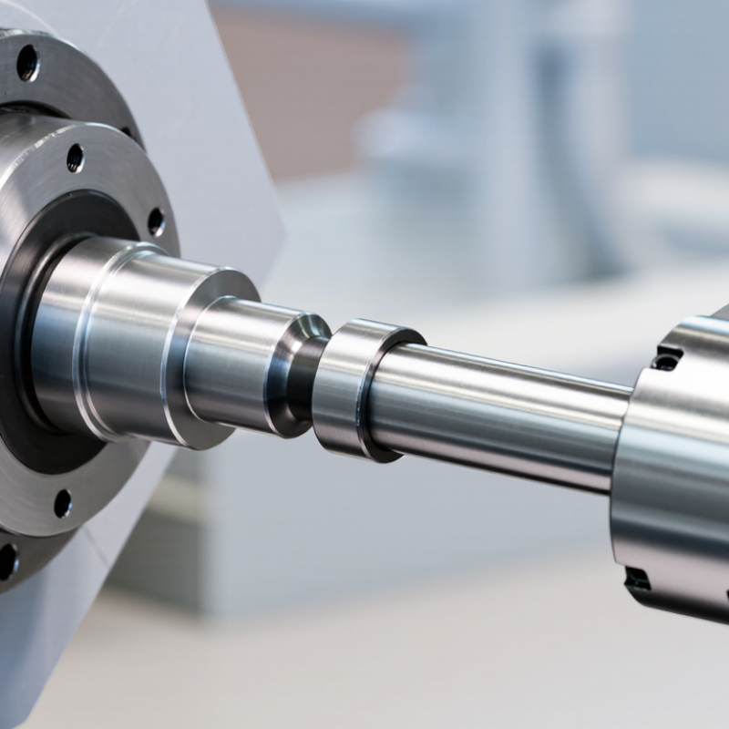
What Is a Sliding Drive Shaft?
A sliding drive shaft is a torque-carrying shaft that can also change length. Its inner and outer splined sections slide against each other, allowing axial movement while the shaft rotates. In a vehicle, that movement can accommodate suspension travel and shifts in the distance between drivetrain components. In industrial equipment, it can help manage movement between connected machines. The splines must transmit torque while sliding; wear, contamination, or poor alignment can make movement stiff and noisy. That sounds simple. It isn’t always.
ISO 4156 specifies dimensions and fits for straight-sided involute splines, which are used in some sliding shaft designs. Correct fit matters: excessive clearance can increase impact and backlash, while tight fits may resist axial travel. The U.S. Department of Energy’s “Where the Energy Goes: Gasoline Vehicles” estimates that roughly 5–6% of vehicle energy is lost through the drivetrain. That figure describes the drivetrain overall, not a sliding shaft alone. A telescoping shaft does not erase those losses; it solves a different problem by accommodating length change while carrying torque.
Tips: Check axial travel, torque demand, operating angle, and lubrication requirements together. Look for polished wear marks or rust around the sliding section during inspection. A shaft that moves by hand when unloaded may still bind under torque, so verify it in its actual operating setup.
| Dimension | Details | Why It Matters |
|---|---|---|
| Definition | A sliding drive shaft is a shaft assembly designed to transmit rotary torque while allowing its effective length to change. Axial movement is commonly provided by a splined slip joint or a telescoping shaft section. | It accommodates movement between connected components without requiring the shaft to remain at one fixed length. |
| How it works | The sliding sections move in or out along the shaft axis while their engaged splines or profiles continue to transfer rotation and torque. | The joint must have enough usable travel for the application and remain properly engaged throughout that travel. |
| Typical applications | Vehicle propeller shafts, agricultural equipment, construction machinery, and other driveline systems where connected components can move relative to one another. | It is useful when suspension travel, articulation, or machine movement changes the distance between drivetrain components. |
| Main benefit | Allows axial length changes while transmitting rotation, reducing the need for a rigid, fixed-length connection. | Can help a driveline accommodate movement that would otherwise place unwanted axial loads on connected components. |
| Length and travel | Required installed length and sliding travel depend on the equipment geometry and its full range of movement. The shaft should not bottom out or lose adequate engagement during operation. | Correct measurement helps prevent binding, separation, and damage to the shaft or connected components. |
| Torque capacity | Capacity depends on factors such as material, shaft diameter, wall thickness, spline design, joint construction, and operating conditions. | Selection should be based on the application’s torque and service requirements, not on sliding capability alone. |
| Alignment and operating angles | The shaft and its joints must operate within the alignment and angular limits specified for the particular equipment and joint design. | Incorrect angles or alignment can contribute to vibration, noise, and accelerated wear. |
| Maintenance considerations | Depending on the design, the sliding joint may require lubrication and inspection for wear, corrosion, looseness, or contamination. | Following the equipment maker’s maintenance guidance helps preserve smooth movement and reliable torque transfer. |
| When to choose one | Choose a sliding drive shaft when the distance between connected drivetrain components changes during normal operation and the assembly must continue transmitting torque. | Confirm the required travel, torque capacity, operating speed, joint angles, dimensions, and maintenance needs before selecting a design. |
A sliding drive shaft uses a splined, telescoping section to transmit torque while allowing its overall length to change. As a vehicle’s suspension rises or falls, the distance between the transmission and driven axle shifts. The inner and outer splines slide relative to each other, accommodating that movement without forcing connected components out of position. Small movement matters.
The shaft needs enough plunge travel for suspension articulation, installation tolerances, and operating changes. It must not bottom out at full compression or lose too much spline engagement at full extension. NIST reference data put carbon steel’s linear thermal expansion near 12 micrometers per meter per degree Celsius. For a 1.5-meter steel shaft and a 40°C temperature change, that is about 0.72 millimeters of length change. It is only an estimate; actual movement depends on material and temperature.
In service, technicians can check plunge travel through the full suspension range, not just at ride height. They should also inspect spline wear, lubrication, and sealing. A dry or contaminated sliding joint may bind, turning normal movement into vibration or extra load on nearby bearings. The part I would verify twice is available travel: geometry on paper can miss real-world suspension angles.
Sliding drive shafts are used wherever torque must pass between components whose distance changes during operation. In agricultural machinery, tractor driveline assemblies and harvesting equipment may use sliding sections to accommodate movement. Mobile construction equipment can also need them when axle positions or working components shift. Industrial applications include conveyors and machines with moving carriages or adjustable sections. The shaft extends or retracts while maintaining a mechanical connection. Movement matters.
Choosing one takes more than matching its length. Engineers check torque, rotational speed, operating angle, travel range, and spline overlap at full extension. A sliding shaft needs enough clearance to move without binding.
Dust, crop residue, and poor alignment can make that harder in real working conditions. Keep guards in place and inspect the sliding section for wear and contamination.
Not every setup. In fixed, well-aligned machinery, a simpler coupling may be easier to maintain.
Actual layouts can be awkward, so allow room for movement and inspection.
A sliding drive shaft transfers torque while allowing its length to change. This is useful when connected components move relative to each other, such as across a vehicle suspension or between a motor and a movable machine section. The sliding joint can accommodate axial travel without forcing the shaft or bearings to absorb every change. That matters.
The benefit depends on the application. A properly sized shaft can simplify installation where space is tight and help maintain power transfer through movement. For example, suspension travel may shorten or extend the distance between drivetrain components. A sliding joint gives that motion somewhere to go. But it does not correct poor alignment, and it still needs adequate torque capacity and operating-speed ratings.
There are trade-offs. Sliding splines can wear, develop backlash, or bind if lubrication is inadequate or dirt enters the joint. More movement can mean more maintenance, not less. Check the required travel, load peaks, shaft angles, and working environment before selecting one. In practice, measuring movement at the extremes is easy to overlook. It is worth repeating, even if the numbers seem obvious. A shaft that works smoothly on a bench may behave differently under vibration, heat, and changing loads.
Choosing a sliding drive shaft starts with the movement it must accommodate. Measure the full axial travel, not just the installed length. The shaft needs enough spline engagement at maximum extension to transmit torque safely. At full compression, it must not bottom out. Leave suitable clearance for movement and manufacturing tolerances.
Next, define the operating conditions. Record peak and continuous torque, rotational speed, working angle, duty cycle, and expected shock loads. A conveyor that starts under load may need a different design from a lightly loaded mixer. Check the shaft’s critical speed and confirm that its rated capacity covers the real operating range. Close enough is not a specification.
Material and protection matter, too. Dust, moisture, heat, and washdown can affect spline wear and lubrication. Select seals and grease suited to the environment, then check how maintenance will be performed. Verify connection dimensions, balance requirements, and mounting space before ordering. A practical check is to mark the shaft’s travel limits on a drawing and compare them with the machine’s actual movement. That detail is easy to miss. If measurements are uncertain, pause and recheck them; a neat calculation can still rest on the wrong datum.
„Thanks to the LUVIR technology, the solder resist process could be switched directly from the previously used mask exposure to direct exposure. As an outstanding digital solution on the market, this technology has been able to demonstrate fast process times and superior quality on our certified conventional ink in production. This allowed us to fully digitize the solder mask process at low cost – without process or ink adjustments. An excellent benefit to our production in Rot am See.“
Ralf Göhringer (Head of Production WE Rot am See)
I would definitely recommend the Limata machine and team for a future company purchase
Michael Greenaway
Compunetics Inc.
“The Limata ldi has been amazing!! Best thing we did was buy this machine”
Richard Brady
GM
Circuitlabs
“Since 2019, we have been running the Limata X1000 LDI system (including LUVIR for solder mask imaging) in daily production as an addition to our current process with film. The machine was capable of properly exposing Taiyo PSR-4000 BN (DI) solder mask types on normal to high-copper boards using a new and unique direct imaging process. The machine operating interface is very user friendly which allowed for a quick technical training curve. The pre-registration processing reduced several seconds of production time at every print. Limata support and service staff is incomparable. They supported our team every step of the way at basically any time of the day or night, with literally, an immediate response time, customizing the software interface to best fit our Operations and needs.
We have exposed more than 8,000 prints since end of October, on various solder mask colors and some resist film panels. Limata, has proven to be very capable and innovative. They are a strong contender in the industry.
We have very much enjoyed this project, and working with the team!
Thank you Limata for the continued support and being a part of our growth.”
Bill Sezate
Vice President, GM
Summit Interconnect
As a replacement to our current contact exposure process with film, the LIMATA X2000 system including LUVIR-Technology was capable of properly exposing non-LDI solder mask types using a direct imaging process. The machine offers cutting edge software with a very intuitive operating interface which allowed for quick technician training curve. The dual drawer system combined with pre-registration processing reduced several seconds of production time at every machine cycle. Limata support and service staff is world class. They added software patches to keep production running at shortest possible response times, customized the software interface to best fit our in-house Operations system, and even wrote a step-by-step machine processing manual. As a result of the project, we have exposed more than 16,000 times on various product types and solder mask brands/colors. Limata, in a very short timeframe as a company, has definitely shown they are truly innovative and will be challenging the industry of direct imaging for the top spot.
Kevin Beattie
Process Engineer
TTM Technologies
Forest Grove Division