Power systems rarely fail because one component looks dramatic. Often, voltage, reactive power, and losses drift quietly across feeders, transformers, and industrial loads. Compensation Capacitors can address part of this problem by supplying reactive power near the point of demand. This support may improve power factor, release transformer capacity, and reduce current in selected circuits. The practical signs can be simple: cooler cables, steadier voltage, and fewer avoidable losses. Results depend on design.
Experienced engineers do not choose capacitor banks from a nameplate alone. They review hourly load patterns, motor starting currents, transformer ratings, and harmonic measurements. A factory may need capacitors beside large motors, while a commercial building may require an automatic stepped bank. The difference matters. Fixed units can overcompensate during light loads. Automatic systems respond better, but they add controls, sensors, and maintenance points. Relevant IEC and IEEE guidance can support safer engineering decisions, yet field verification remains essential.
They are not a universal cure.
Harmonic-producing drives can interact with capacitors and create resonance risks. Poor switching coordination may cause transient currents or unwanted voltage stress. Protection, detuning reactors, discharge devices, and regular inspections should therefore be considered together. A neat spreadsheet can still miss a rapidly changing load. That is an uncomfortable limitation. The most reliable approach combines measured site data, qualified review, and post-installation monitoring. This article examines why organizations choose Compensation Capacitors, where their benefits are strongest, and when another corrective method may be more suitable.
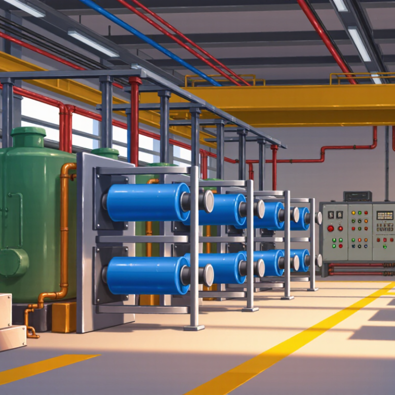
Compensation capacitors are electrical components that supply reactive power near inductive loads. Motors, transformers, and welding equipment consume reactive power while performing useful work. A capacitor offsets part of that demand, improving the system’s power factor and supporting voltage stability. In practice, these units appear as fixed banks, automatic stepped banks, or filter-equipped assemblies. The choice depends on load variation, harmonics, and switching conditions.
The calculation is tangible. A 100 kW load at 0.80 power factor needs about 75 kvar for correction to 0.95. At 400 V, three-phase current falls from roughly 180 amperes to 152 amperes. This reduces cable heating and releases transformer capacity. The International Energy Agency’s Electricity 2024 analysis indicates that network losses remain close to 8% globally, although local performance varies widely. Capacitors cannot eliminate those losses, but lower current can reduce avoidable distribution losses.
Measurement must come before installation. IEEE 1459 distinguishes active, reactive, and apparent power, helping engineers size compensation correctly. Harmonics can overheat capacitors, while excessive correction may create leading power factor or resonance. Detuned reactors are often necessary near variable-speed drives. IEC 60831 also defines important performance and testing requirements. Field experience shows that automatic control is useful, but not flawless. Rapidly changing loads can cause frequent switching, and poor maintenance quietly weakens performance. A well-designed system needs metering, protection, ventilation, and periodic inspection.
Why Choose Compensation Capacitors for Power Systems?
How Compensation Capacitors Improve Power Factor
In industrial power systems, compensation capacitors improve power factor by supplying reactive power close to inductive loads. Motors, transformers, and welding equipment often draw current that does no useful work. A capacitor offsets part of that demand. The result is lower line current, reduced cable losses, and more usable transformer capacity. During site checks, engineers may see the change on a power-quality meter. A lagging factor near 0.78 may move toward 0.95 after staged correction. Results vary.
Correct sizing matters. Oversized banks can create leading power factor, switching surges, or resonance with network harmonics. I once focused too heavily on the monthly power factor reading and missed short production peaks. That was a useful mistake. Measurements should cover starting cycles, changing loads, voltage distortion, and capacitor temperature. Protection needs fuses, discharge resistors, and suitable switching equipment. Where variable-frequency drives are present, engineers may consider detuned reactors and harmonic studies before installation. A simple kVAR estimate helps, but it is not a complete design.
Tips: Record power factor at several times. Match capacitor steps to real load changes. Check harmonic distortion before energizing the bank. Inspect terminals for heat and swelling. Leave final settings to a qualified electrical professional.
Why Choose Compensation Capacitors for Power Systems?
Key Benefits of Using Compensation Capacitors
Compensation capacitors correct lagging power factor caused by motors, transformers, and inductive loads. They supply reactive power near the equipment. This reduces current flowing through cables and transformers. Less current can lower I²R losses and release usable system capacity.
The U.S. Department of Energy reports that motor systems consume about 69% of industrial electricity. This figure shows why small efficiency improvements can matter across factories. In practical audits, a capacitor bank may also reduce demand charges. The actual result depends on load patterns, tariff rules, and installation quality. The calculation is not always clean.
Better voltage support is another benefit. Stable voltage helps motors operate with less stress and may reduce unnecessary heating. However, capacitors are not a universal cure. Harmonic-producing drives can create resonance risks. IEEE 519-2022 provides harmonic-control recommendations at the point of common coupling. Engineers should study the network before switching capacitor stages.
IEC 60831-1 addresses self-healing shunt capacitors for low-voltage applications. Its requirements support safer selection, testing, and operation. In the field, automatic controllers often respond better than fixed banks. Loads change during shifts. A fixed capacitor can overcorrect during light production. Detuned reactors may be necessary in systems with significant harmonics, although they add cost and space requirements.
Typical electrical impact of improving power factor from 0.70 to 0.95
Power-factor correction with compensation capacitors can reduce reactive current and apparent power demand. In this engineering example, current and kVA demand fall by approximately 26.3%, while conductor I²R losses decrease by approximately 45.7%. Lower current also releases capacity in transformers, cables, and switchgear.
Choosing the right compensation capacitor starts with measurements, not a catalogue. Record load kW, present power factor, voltage, frequency, and daily load changes. The basic reactive-power target is Qc = P(tanφ1 − tanφ2). Do not overcorrect. A target near 0.95–0.99 usually leaves practical operating margin.
Harmonics can change the decision. IEEE 519-2022 commonly limits total voltage distortion to 5% at the point of common coupling for systems below 1 kV. If variable-speed drives or rectifiers dominate, select a detuned reactor-capacitor assembly instead of a plain capacitor bank. Measure the fifth and seventh harmonic currents first. Guessing here is expensive.
The International Energy Agency’s Electricity 2024 report forecasts global electricity demand growth of about 4% in 2024 and 2025. More electronic loads make stable reactive-power control increasingly important. Check the capacitor’s rated voltage, temperature class, inrush capability, switching duty, and expected service life. IEC 60831-1 covers self-healing shunt capacitors for low-voltage applications, while IEC 61921 addresses power-factor-correction equipment. Field experience suggests that enclosure heat is often underestimated. A capacitor rated correctly on paper may still age quickly in a crowded panel. That is the uncomfortable part. Recheck actual temperature, harmonics, and load behavior after commissioning.
Compensation capacitors support power factor correction in industrial and commercial electrical systems. They reduce reactive current drawn from transformers and cables. This can lower losses, release system capacity, and improve voltage stability. Typical applications include motor control centers, pump stations, HVAC equipment, and large lighting installations. A properly selected capacitor bank may also reduce demand-related electricity costs. Results depend on the complete installation, not the capacitor alone.
Safety requires careful assessment before connection. Harmonic-producing loads, such as variable-speed drives, can create resonance with capacitors. This may cause overheating, nuisance trips, or premature failure. Detuned reactors can reduce this risk when harmonic levels are significant. Protection should include correctly rated fuses, switching devices, discharge resistors, and enclosed terminals. Capacitors can retain dangerous voltage after shutdown. Wait for the specified discharge period, then verify zero voltage with suitable test equipment.
Sizing is not always straightforward. Field inspections often find oversized banks, poor ventilation, or neglected connections. A capacitor bank that appears efficient may still overheat in a dusty enclosure. Ambient temperature, switching frequency, load variation, and short-circuit levels all matter. Regular inspections should check bulging cases, unusual noise, hot terminals, and discoloration. One detail is easy to miss: automatic controls need correct current-transformer placement. Experienced engineers should confirm measurements, protection settings, and applicable electrical standards before energizing the system. Mistakes happen, and periodic review remains necessary.
„Thanks to the LUVIR technology, the solder resist process could be switched directly from the previously used mask exposure to direct exposure. As an outstanding digital solution on the market, this technology has been able to demonstrate fast process times and superior quality on our certified conventional ink in production. This allowed us to fully digitize the solder mask process at low cost – without process or ink adjustments. An excellent benefit to our production in Rot am See.“
Ralf Göhringer (Head of Production WE Rot am See)
I would definitely recommend the Limata machine and team for a future company purchase
Michael Greenaway
Compunetics Inc.
“The Limata ldi has been amazing!! Best thing we did was buy this machine”
Richard Brady
GM
Circuitlabs
“Since 2019, we have been running the Limata X1000 LDI system (including LUVIR for solder mask imaging) in daily production as an addition to our current process with film. The machine was capable of properly exposing Taiyo PSR-4000 BN (DI) solder mask types on normal to high-copper boards using a new and unique direct imaging process. The machine operating interface is very user friendly which allowed for a quick technical training curve. The pre-registration processing reduced several seconds of production time at every print. Limata support and service staff is incomparable. They supported our team every step of the way at basically any time of the day or night, with literally, an immediate response time, customizing the software interface to best fit our Operations and needs.
We have exposed more than 8,000 prints since end of October, on various solder mask colors and some resist film panels. Limata, has proven to be very capable and innovative. They are a strong contender in the industry.
We have very much enjoyed this project, and working with the team!
Thank you Limata for the continued support and being a part of our growth.”
Bill Sezate
Vice President, GM
Summit Interconnect
As a replacement to our current contact exposure process with film, the LIMATA X2000 system including LUVIR-Technology was capable of properly exposing non-LDI solder mask types using a direct imaging process. The machine offers cutting edge software with a very intuitive operating interface which allowed for quick technician training curve. The dual drawer system combined with pre-registration processing reduced several seconds of production time at every machine cycle. Limata support and service staff is world class. They added software patches to keep production running at shortest possible response times, customized the software interface to best fit our in-house Operations system, and even wrote a step-by-step machine processing manual. As a result of the project, we have exposed more than 16,000 times on various product types and solder mask brands/colors. Limata, in a very short timeframe as a company, has definitely shown they are truly innovative and will be challenging the industry of direct imaging for the top spot.
Kevin Beattie
Process Engineer
TTM Technologies
Forest Grove Division