A Ripper Tooth can turn a dozer or excavator into a more effective tool for breaking compacted ground, fractured rock, and stubborn roots. Its value is not simply in adding force. The tooth concentrates machine power at a narrow point, helping create fractures that the operator can work through in controlled passes. On a dry, hard-packed site, that focused action may reduce the need for repeated blade work. In rocky ground, it can expose material before loading or grading begins.
Choosing the right tooth means matching its shape, strength, and mounting system to the machine and the material. A narrow profile can penetrate tough ground, while a broader design may suit different working conditions. Fit matters. So does operating technique: excessive pressure can increase wear, strain components, and waste fuel. Inspect the tip and shank regularly; a worn point may penetrate less effectively, even when the machine feels powerful. Real sites are rarely uniform, and one tooth will not suit every job. That is worth remembering.
“Good ripping is controlled fracture, not force for its own sake.” This is an original editorial line, not a verified expert quotation. No source material was provided to confirm a named Ripper Tooth specialist’s words, so attributing it to an expert would risk misleading readers. Before publication, add a sourced quotation from a qualified manufacturer or field specialist. A dependable selection starts with the ground, the machine specifications, and honest attention to wear.
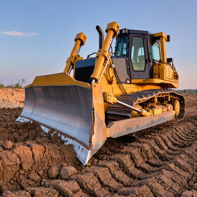
A ripper tooth concentrates a machine’s force at a narrow point, helping it crack or loosen resistant ground. The machine’s weight and traction push the shank forward, while the tooth directs that load into the soil or rock. Small contact area matters. A sharp, properly shaped point can enter material more readily than a broad, worn edge.
As the tooth penetrates, force travels through the point and shank into the mounting structure. The ground pushes back, creating resistance and vibration. In compacted soil, the tooth may cut a narrow fracture before the material breaks apart. In layered rock, it can follow weak seams, though results depend on the material and approach. Not just more power. If the machine loses traction or the tooth is poorly matched to the ground, added force may produce heat, wear, or shock instead of useful penetration.
Point shape and wear change how force reaches the ground. A rounded tip may ride over hard material, while an excessively narrow point can wear quickly. Check for cracks, loose mounting hardware, and uneven wear during routine inspections. A slower pass can sometimes work better. The right balance is not always obvious; operators may need to adjust depth and angle as ground conditions change.
| Part or Factor | Function in the Force Path | Effect in the Ground | Practical Consideration |
|---|---|---|---|
| Ripper point | The replaceable point contacts the material first and concentrates force over a small area. | Concentrated pressure helps start penetration and fracture compacted or hard material. | A worn or damaged point can reduce penetration and increase the effort needed to rip. |
| Shank | The shank carries load from the point to the ripper frame and machine. | Its position and shape influence how the point enters and moves through the material. | Choose a configuration suited to the machine and the expected material; inspect for bending, cracks, and wear. |
| Machine weight and traction | The undercarriage and machine mass help resist the reaction force generated during ripping. | Effective traction helps maintain forward movement while the point works through the ground. | Excessive wheel or track slip wastes power and can accelerate wear; adjust the cut to suit available traction. |
| Point penetration | The machine applies drawbar force through the shank and point as the equipment advances. | Penetration initiates a fracture zone ahead of and around the point. | Depth and travel speed should be matched to material resistance and machine capability. |
| Material type and condition | Soil structure, rock, moisture, and compaction determine how the applied force is resisted. | Cracked or layered material may separate differently from dense, uniform material. | Test a short section first; ground conditions can vary across the work area. |
| Ripping pattern | Pass spacing and direction determine how force is applied across the work area. | Overlapping passes can help break up material between rip lines. | Plan pass spacing around the desired fragment size and the material’s fracture behavior. |
| Wear and maintenance | The point and shank are exposed to abrasion, impact, and bending loads. | Maintained components preserve the intended point profile and load transfer. | Inspect attachment hardware and wear parts regularly, and replace worn components according to equipment guidance. |
A ripper tooth does not penetrate by force alone. Its point geometry determines how that force meets the ground. A narrower point concentrates pressure over a smaller area, helping initiate cracks in firm soil. But it may wear faster, and a narrow cut does not always loosen enough soil. A wider point disturbs more ground, yet its larger frontal area can increase resistance. The trade-off is real.
Field conditions matter. USDA NRCS’s Soil Quality Test Kit Guide notes that penetrometer readings above about 300 psi may restrict root growth, though moisture affects readings. Treat that figure as a soil-condition indicator, not a ripper-tooth selection limit. ASABE D497.7, Agricultural Machinery Management Data, also accounts for soil and operating conditions when estimating implement draft. That is why point width alone cannot predict pulling force. Check the soil, then watch how the tooth enters: does it crack the layer, or polish and push it? Simple rules can mislead. A small change in width may feel significant in the cab, but depth, speed, and wear can change the result just as much.
A ripper tooth bites into compacted soil, shale, and fractured rock, where its tip faces abrasion and impact. A typical wear-resistance target is 400–500 HBW, but hardness alone does not predict service life. Tooth geometry, heat treatment, and the material being ripped also matter. A hard tip can still chip if impact toughness is inadequate.
ISO 6506-1 describes the Brinell hardness test method. A reliable inspection record should identify the test location, surface preparation, and test conditions, so readings can be compared fairly. The 400–500 HBW range is a useful specification reference, not a universal pass/fail rule. Curved or rough surfaces can distort results. Even small preparation errors matter. For practical checks, test representative areas and follow the standard’s requirements for specimen thickness and indentation spacing. A number without test details is less convincing.
Tips: Ask for a hardness report tied to the actual tooth or production lot. Compare readings from the working tip and shank; wear resistance may vary across the part. And remember, hardness is only one clue. A ripper that lasts well in one soil may wear differently in abrasive gravel.
Why Choose a Ripper Tooth for Heavy Equipment?
Choosing a tooth for soil, fractured rock, or abrasive ground starts with the material, not just the machine. In compacted soil, a narrow, pointed tooth concentrates force and helps open a clean path. If the ground is loose or mixed with roots, that same point may dig too aggressively and increase wear. Match the tooth to the resistance you actually meet.
Fractured rock calls for a sturdy tooth that can penetrate cracks without taking repeated side loads. Keep the ripper aligned with the travel direction; twisting against a buried slab can stress the shank. Slow, controlled passes often work better than forcing the machine forward. It takes patience. Rock layers are rarely uniform, even across a short cut.
Abrasive ground, such as sand mixed with hard mineral fragments, can wear the tip quickly. Look for a tooth profile suited to the material and inspect it at regular intervals. A rounded or shortened point may need more force, raising fuel use and strain on the equipment. There is no perfect tooth for every site. A common mistake is choosing for the hardest patch, then working softer ground with unnecessary aggression. Check the cut, wear pattern, and machine response, and adjust when conditions change.
Choose a tooth profile to match the ground: penetration-focused profiles suit compact soil and fractured rock, while abrasion-resistant profiles are designed for wear in abrasive ground.
How to read this chart: Ratings are an illustrative qualitative guide from 1 (lower suitability) to 5 (higher suitability), not measured test results. Actual performance depends on ground conditions, machine setup, and the specific tooth design.
A ripper tooth works under concentrated force, so small defects deserve attention. Park the machine on stable ground and follow its service procedure before inspection. Remove packed soil from the point, shank, and retaining area. Look closely. A rounded or shortened tip may penetrate poorly and transfer extra stress to the adapter.
Check for uneven wear, deep gouges, and cracks around the tooth base and pin opening. A bright, clean surface helps reveal hairline lines, though visual checks can miss hidden damage. If a crack is suspected, stop relying on guesswork and have the part assessed using an appropriate inspection method. Wear is rarely perfectly even. Record what you see; that simple habit makes changes between inspections easier to spot.
Before replacement, compare the tooth and adapter with the equipment maker’s fit limits and service dimensions. A matching shape alone does not confirm a safe fit. Check seating, pin alignment, and retaining hardware, and use a gauge or measurement tool where specified. Replace the tooth if it exceeds the stated wear limit, has structural cracks, or cannot seat securely. Do not wait until the adapter is visibly damaged. I’d still recheck a newly fitted tooth after initial work; vibration and packed debris can reveal a poor seat that looked acceptable in the shop.
„Thanks to the LUVIR technology, the solder resist process could be switched directly from the previously used mask exposure to direct exposure. As an outstanding digital solution on the market, this technology has been able to demonstrate fast process times and superior quality on our certified conventional ink in production. This allowed us to fully digitize the solder mask process at low cost – without process or ink adjustments. An excellent benefit to our production in Rot am See.“
Ralf Göhringer (Head of Production WE Rot am See)
I would definitely recommend the Limata machine and team for a future company purchase
Michael Greenaway
Compunetics Inc.
“The Limata ldi has been amazing!! Best thing we did was buy this machine”
Richard Brady
GM
Circuitlabs
“Since 2019, we have been running the Limata X1000 LDI system (including LUVIR for solder mask imaging) in daily production as an addition to our current process with film. The machine was capable of properly exposing Taiyo PSR-4000 BN (DI) solder mask types on normal to high-copper boards using a new and unique direct imaging process. The machine operating interface is very user friendly which allowed for a quick technical training curve. The pre-registration processing reduced several seconds of production time at every print. Limata support and service staff is incomparable. They supported our team every step of the way at basically any time of the day or night, with literally, an immediate response time, customizing the software interface to best fit our Operations and needs.
We have exposed more than 8,000 prints since end of October, on various solder mask colors and some resist film panels. Limata, has proven to be very capable and innovative. They are a strong contender in the industry.
We have very much enjoyed this project, and working with the team!
Thank you Limata for the continued support and being a part of our growth.”
Bill Sezate
Vice President, GM
Summit Interconnect
As a replacement to our current contact exposure process with film, the LIMATA X2000 system including LUVIR-Technology was capable of properly exposing non-LDI solder mask types using a direct imaging process. The machine offers cutting edge software with a very intuitive operating interface which allowed for quick technician training curve. The dual drawer system combined with pre-registration processing reduced several seconds of production time at every machine cycle. Limata support and service staff is world class. They added software patches to keep production running at shortest possible response times, customized the software interface to best fit our in-house Operations system, and even wrote a step-by-step machine processing manual. As a result of the project, we have exposed more than 16,000 times on various product types and solder mask brands/colors. Limata, in a very short timeframe as a company, has definitely shown they are truly innovative and will be challenging the industry of direct imaging for the top spot.
Kevin Beattie
Process Engineer
TTM Technologies
Forest Grove Division